AVAYA DOCUMENTATION CENTER
Find answers to your technical questions and learn how to use our products
Deploying Avaya Aura® Communication Manager in Virtualized Environment
VMware networking best practices
You can administer networking in a VMware environment for many different configurations. The examples in this section describe some of the VMware networking possibilities.
This section is not a substitute for the VMware documentation. Review the VMware networking best practices before deploying any applications on an ESXi host.
The following are the suggested best practices for configuring a network that supports deployed applications on VMware Hosts:
Separate the network services to achieve greater security and performance by creating a vSphere standard or distributed switch with dedicated NICs for each service. If you cannot use separate switches, use port groups with different VLAN IDs.
Configure the vMotion connection on a separate network devoted to vMotion.
For protection, deploy firewalls in the virtual machines that route between virtual networks that have uplinks to physical networks and pure virtual networks without uplinks.
Specify virtual machine NIC hardware type vmxnet3 for best performance.
Connect all physical NICs that are connected to the same vSphere standard switch to the same physical network.
Connect all physical NICs that are connected to the same distributed switch to the same physical network.
Configure all VMkernel vNICs to be the same IP Maximum Transmission Unit (MTU).
Disclaimer: The images in this section represent older ESXi versions and may vary for the latest ESXi versions.
Networking Avaya applications on VMware ESXi – Example 1
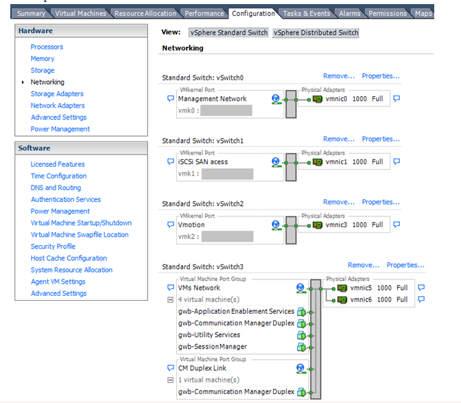
This configuration describes a simple version of networking Avaya applications within the same ESXi host. Highlights to note:
Separation of networks: VMware Management, VMware vMotion, iSCSI (SAN traffic), and virtual machine networks are segregated to separate physical NICs.
Teamed network interfaces: vSwitch 3 in Example 1 displays use of a load-balanced NIC team for the Virtual Machines Network. Load balancing provides additional bandwidth for the Virtual Machines Network, while also providing network connectivity for the virtual machines in the case of a single NIC failure.
Communication Manager Duplex link: Communication Manager software duplication must be separated from all other network traffic. Example 1 displays one method of separating Communication Manager Duplex with a port group combined with a VLAN. The Communication Manager software duplication link must meet specific network requirements. For more information, see Avaya PSN003556u at PSN003556u. The following are the minimum requirements of the Communication Manager software duplex connectivity:
The total capacity must be 1 Gbps or greater. Reserve 50 Mbps of bandwidth for duplication data.
The round-trip delay must be 8 ms or less.
The round-trip packet loss must be 0.1% or less.
Both servers’ duplication ports must be on the same IP subnet.
You must disable duplication link encryption for busy-hour call rates that result in greater than 40% CPU occupancy. You can view the CPU occupancy using the list measurements occupancy command and looking at the results under the Static + CPU occupancy heading.
The system must maintain CPU occupancy on the active server (Static + CPU) at less than 65% to provide memory refresh from the active to standby server.
Session Manager vNIC mapping: Session Manager OVA defines four separate virtual NICs within the VM. However, example 1 shows all interfaces networked through a single virtual machine network, which is supported. If the Session Manager Management and Session Manager Asset networks are separated by subnets, you can create a VLAN for the appropriate network.
Virtual networking: The network connectivity between virtual machines that connect to the same vSwitch is entirely virtual. In example 2, the virtual machine network of vSwitch3 can communicate without entering the physical network. Virtual networks benefit from faster communication speeds and lower management overhead.
Networking Avaya applications on VMware ESXi – Example 2
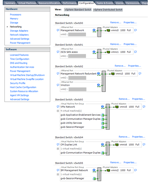
This configuration shows a complex situation using multiple physical network interface cards. The key differences between example 1 and example 2 are:
VMware Management Network redundancy: Example 2 includes a second VMkernel Port at vSwitch2 to handle VMware Management Network traffic. In the event of a failure of vmnic0, VMware Management Network operations can continue on this redundant management network.
Removal of Teaming for Virtual Machines Network: Example 2 removes the teamed physical NICs on vSwitch3. vSwitch3 was providing more bandwidth and tolerance of a single NIC failure instead of reallocating this NIC to other workloads.
Communication Manager Duplex Link: vSwitch4 is dedicated to Communication Manager Software Duplication. The physical NIC given to vSwitch4 is on a separate physical network that follows the requirements described in PSN003556u at PSN003556u.
Session Manager Management Network: Example 2 shows the Session Manager Management network separated onto its own vSwitch. The vSwitch has a dedicated physical NIC that physically segregates the Session Manager Management network from other network traffic.
References
Title |
Link |
|---|---|
Product Support Notice PSN003556u |
Go to https://support.avaya.com and search for PSN003556u. |
VMware vSphere 8.0 Documentation |
Go to Broadcom website (formerly known as VMware) and search for VMware vSphere 8.0 Documentation. |
VMware vSphere 7.0 Documentation |
Go to Broadcom website (formerly known as VMware) and search for VMware vSphere 7.0 Documentation. |