AVAYA DOCUMENTATION CENTER
Find answers to your technical questions and learn how to use our products
Deploying Avaya Session Border Controller on a Hardware Platform
Connecting the servers to the network
After the Avaya SBC servers have been properly installed, you must connect the networking cables. The connection of the Avaya SBC servers to the network is determined by the particular configuration of the enterprise network and the desired location of the server with that topology.
Caution:
Do not interrupt existing network connections without being thoroughly certain of how Avaya SBC is integrated into existing operations. If you are uncertain how to proceed, call Avaya Customer Service for assistance.
Connection summary and considerations
The following table summarizes how each interface connection is used.
Interface |
Usage |
|---|---|
A1 |
The A1, A2, B1, and B2 Ethernet interfaces connect to trusted (internal) networks and untrusted (public) networks. Typically, you will use one pair of interfaces to connect within the trusted network and one pair of interfaces to connect to the untrusted network. In some connectivity solutions, you will bond A1 to A2 and B1 to B2 to expand the bandwidth of the interfaces. |
A2 |
|
B1 |
|
B2 |
|
M1 |
The M1 interface is used for the connection to the Graphical User Interface (GUI) on a combined Avaya SBC and EMS server, or for a dedicated EMS server. For all servers, M1 is also used for the SSH-based Command Line Interface (CLI). |
M2 |
The M2 interface is used for the connection between a pair of Primary and Secondary Avaya SBC HA servers or a pair of active/active EMS servers. The connection is made using a straight or patch Ethernet cable. |
VGA |
The VGA interface is used only for the connection to the CLI. |
Consider the following when connecting Avaya SBC components:
When Avaya devices are all in the same subnet, you must use a one-cable deployment. For example, use only interface A1 instead of using interfaces A1 and B1 (signaling and media interfaces). When Avaya devices are all within the DMZ, the use of internal or external firewalls is optional, depending upon the deployment.
There is no GUI connection available on a dedicated Avaya SBC-only component.
Connectivity diagrams
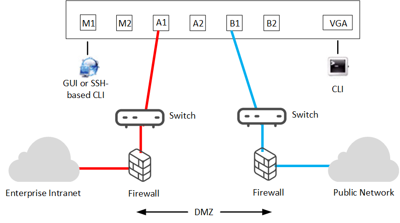
If there is a single combined Avaya SBC and EMS server, the deployment process is run on the combined server and both types of software are deployed.
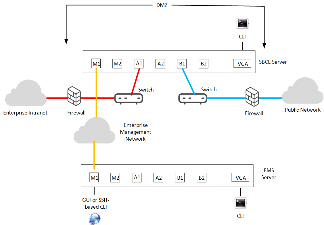
If there is a single Avaya SBC server being managed by a single EMS server, the deployment process is first run remotely on the EMS server. The system then runs the deployment process remotely on the Avaya SBC server.
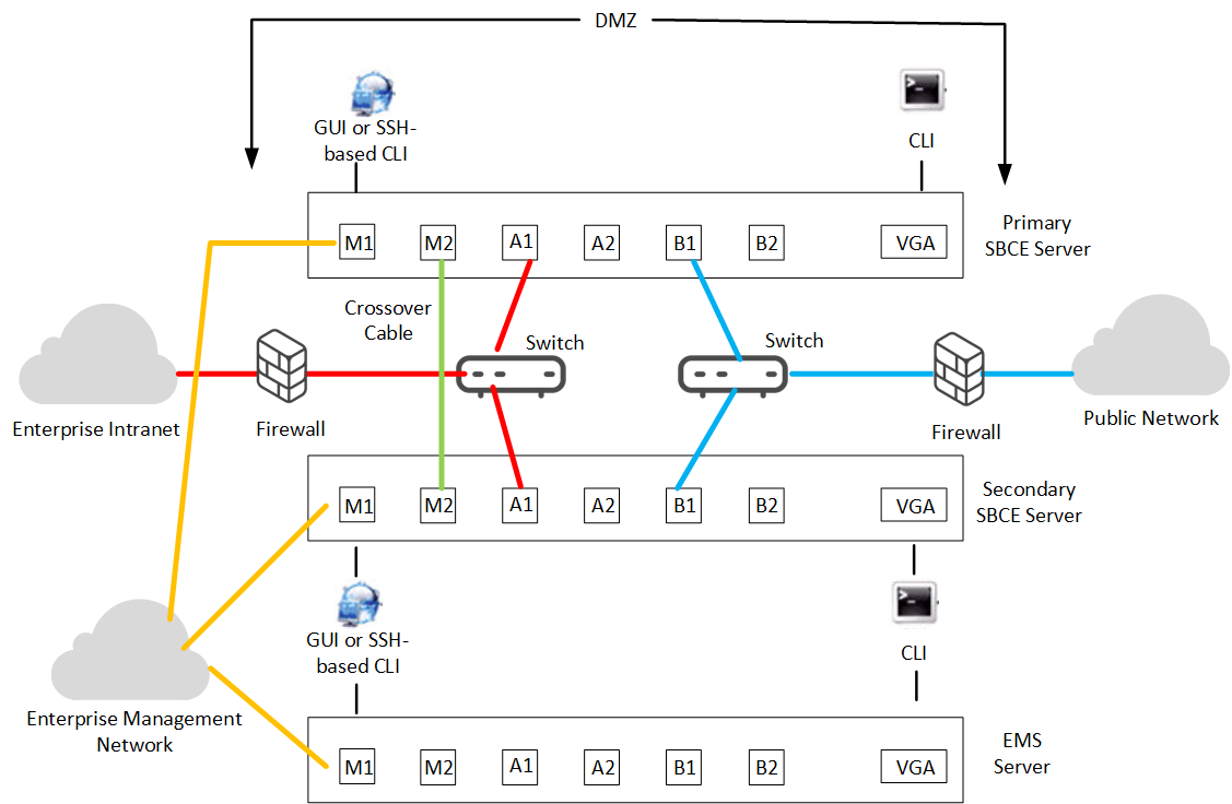
If there are a pair of Avaya SBC HA servers being managed by a single EMS server, the deployment process is first run remotely on the EMS server. The system then runs the deployment process remotely on each of the Avaya SBC servers.
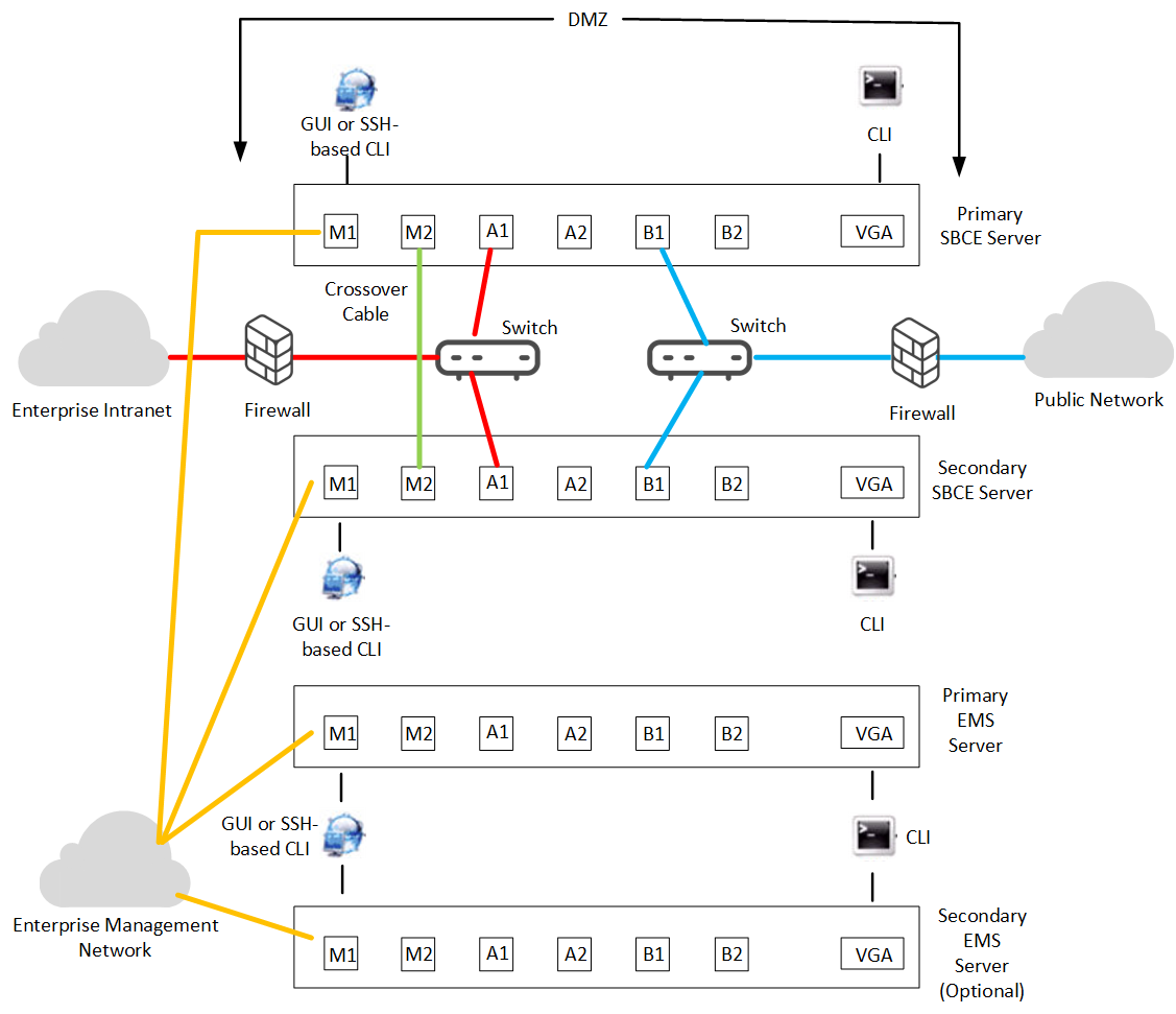
If there are a pair of Avaya SBC HA servers being managed by a pair of active/active EMS servers, the deployment process is first run remotely on the EMS servers, primary first followed by the secondary. The system then runs the deployment process remotely on each of the Avaya SBC servers.