

AVAYA DOCUMENTATION CENTER
Find answers to your technical questions and learn how to use our products
Using Avaya J159 SIP IP Phone in Avaya Aura®
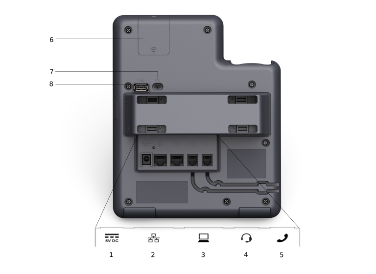
Connection jacks of a J159 IP Phone
The following image illustrates the connection jacks that are present on the back panel of Avaya J159 IP Phone.
The image schematically describes which device to connect to which jack.
|
No.
|
Name
|
Description
|
|---|---|---|
|
1
|
5V DC Jack
|
To connect the power supply.
|
|
2
|
Network port
|
To connect the Ethernet cable.
|
|
3
|
PC port
|
To connect the computer.
Note:
PC port is disabled when a Wi-Fi network is used.
|
|
4
|
Headset Jack
|
To connect the headset.
|
|
5
|
Handset Jack
|
To connect the handset.
|
|
6
|
WLAN Module Panel
|
To integrate the wireless module for Wi-Fi and Bluetooth support.
|
|
7
|
PoE Slide Switch
|
To set the PoE value to one of the following:
|
|
8
|
USB Port
|
To connect the USB device.
|