AVAYA DOCUMENTATION CENTER
Find answers to your technical questions and learn how to use our products
Avaya Session Border Controller Overview and Specification
Multi-tenancy
Configuration example 1 : Multi-tenancy using multiple tenants, call servers, and Avaya SBC interfaces
Avaya SBC achieves multi-tenancy using multiple tenants, call servers, and Avaya SBC interfaces.
This scenario uses all four Avaya SBC data interfaces. Avaya SBC connects to two tenant networks, each with a unique set of remote workers. Avaya SBC also connects to three other networks, each with a call server. Each call server is reached through a separate physical interface, which provides a measure of redundancy when one or more call servers stop responding.
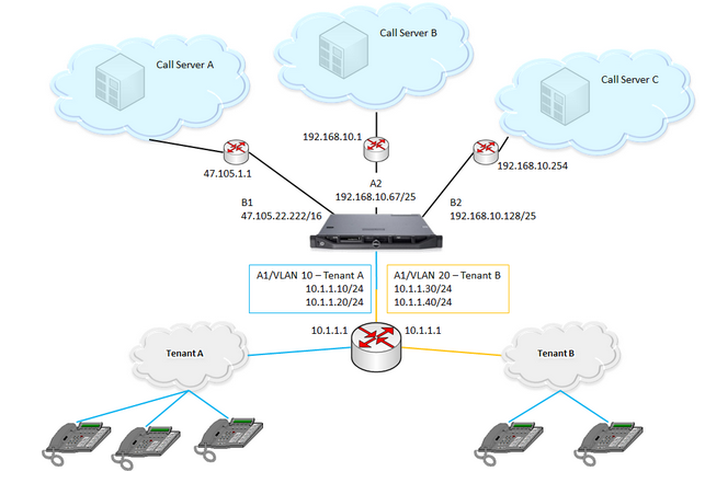
Interfaces and purposes: The A1 interface of Avaya SBC provides connectivity to tenant subnets. Each subnet uses a unique VLAN tag: tenant A (in blue) is on VLAN 10, while tenant B (in orange) uses VLAN 20. The gateway router on the A1 interface provides connectivity to both tenant VLANs.
The B1 interface provides connectivity to call server A, A2 connects Avaya SBC to call server B, and B2 connects the network containing call server C.
Note:You can attach tenants to the B1 interface and connect call server A through the A1 interface. The physical ports retain their historical names: A1, A2, B1, and B2.
Surrounding networking equipment: This configuration supports corresponding mapping between SBC NICs and physical server NICs. Configure the gateway on the A1 interface to support VLAN 10 and VLAN 20, and the associated gateway IP addresses. You do not need to configure the other three gateways on A2, B1, or B2 separately. If Avaya SBC is running on a virtual machine, configure VMWare vSwitch and the physical interfaces on the server. If each physical interface on Avaya SBC uses a separate vSwitch and each vSwitch connects to a separate physical interface on the server, connect vSwitch to a physical port setup. Configure up to four vSwitches.
Avaya SBC Network interfaces: When you configure VLANs on Avaya SBC, the first step is always to create the VLAN interfaces. In this example, two VLAN interfaces are created to support the two tenant networks. First, the VLAN for tenant A on interface A1. Then, the VLAN for tenant B on A1. The remaining networks use physical interfaces on Avaya SBC. Finally, enable all the interfaces: the two VLANs as well as A2, B1, and B2.
Networks connected to Avaya SBC: In this example, Avaya SBC is attached to five networks. For each attached network, define a default gateway router, beginning with tenant A, followed by tenant B, call server A, call server B, and finally call server C.
Configuration Example 2 : Multi-tenancy using the same IP address
Avaya SBC supports the use of the same IP address on multiple data interfaces in Avaya SBC. Customers often share the same address space and service IP address while using multitenant and cloud features. With support for using the same IP address more than one time, more than one customer can use the same IP address to connect to Avaya SBC.

To permit the use of multiple instances of the same IP, the instances must exist on separate network interfaces, virtual network interfaces, or both. Avaya SBC separates interface definition from network definition as follows:
An interface is a combination of a physical port such as A1, A2, B1, and B2, and a vlan ID. A vlan ID can be no vlan.
A network ties a set of Avaya SBC IPs and gateways with an interface.
Therefore, for two instances of 1.2.3.0 on Avaya SBC, you must define two interfaces and two networks, so that 1.2.3.0 occurs exactly once within each network.
In this scenario, Avaya SBC connects to two tenant networks, each with a unique set of remote workers. However, the same IP address is assigned on Avaya SBC on both the tenant networks.

The following sections describe the configuration details for this deployment example.
Interfaces and purposes:
The A1 interface of Avaya SBC provides connectivity to tenant subnets. Each subnet uses a unique VLAN tag: tenant A, highlighted in blue, is on VLAN 10, while tenant B, highlighted in orange, uses VLAN 20. The gateway router on the A1 interface provides connectivity to both tenant VLANs.
The B1 interface provides connectivity to call server A, A2 connects Avaya SBC to call server B, and B2 connects the network containing call server C.
Surrounding networking equipment:
Configure the gateway on the A1 interface to support VLAN 10 and VLAN 20, and the associated gateway IP addresses. As the Avaya SBC address on both tenants is the same, the gateway must be able to distinguish between the addresses for both tenant networks.
Network interfaces:
To use the same IP address on Avaya SBC multiple times, select the Allow Non-unique IPs for Complex Networks field on the Network Options page. To configure VLANs on Avaya SBC, create VLAN interfaces. In this example, two VLAN interfaces are created to support the two tenant networks:
The VLAN for tenant A on interface A1
The VLAN for tenant B on A1
The remaining networks use physical interfaces on Avaya SBC. Finally, enable all the interfaces: the two VLANs as well as A2, B1, and B2.
In this example, the Avaya SBC is attached to five networks. For each attached network, define a default gateway router and Avaya SBC IP addresses. Begin with tenant A, followed by tenant B, call server A, call server B, and finally call server C.