

AVAYA DOCUMENTATION CENTER
Find answers to your technical questions and learn how to use our products
Using Avaya J169 and J179 SIP IP Phones in Avaya Aura®
Connection jacks for J169/179 IP Phone
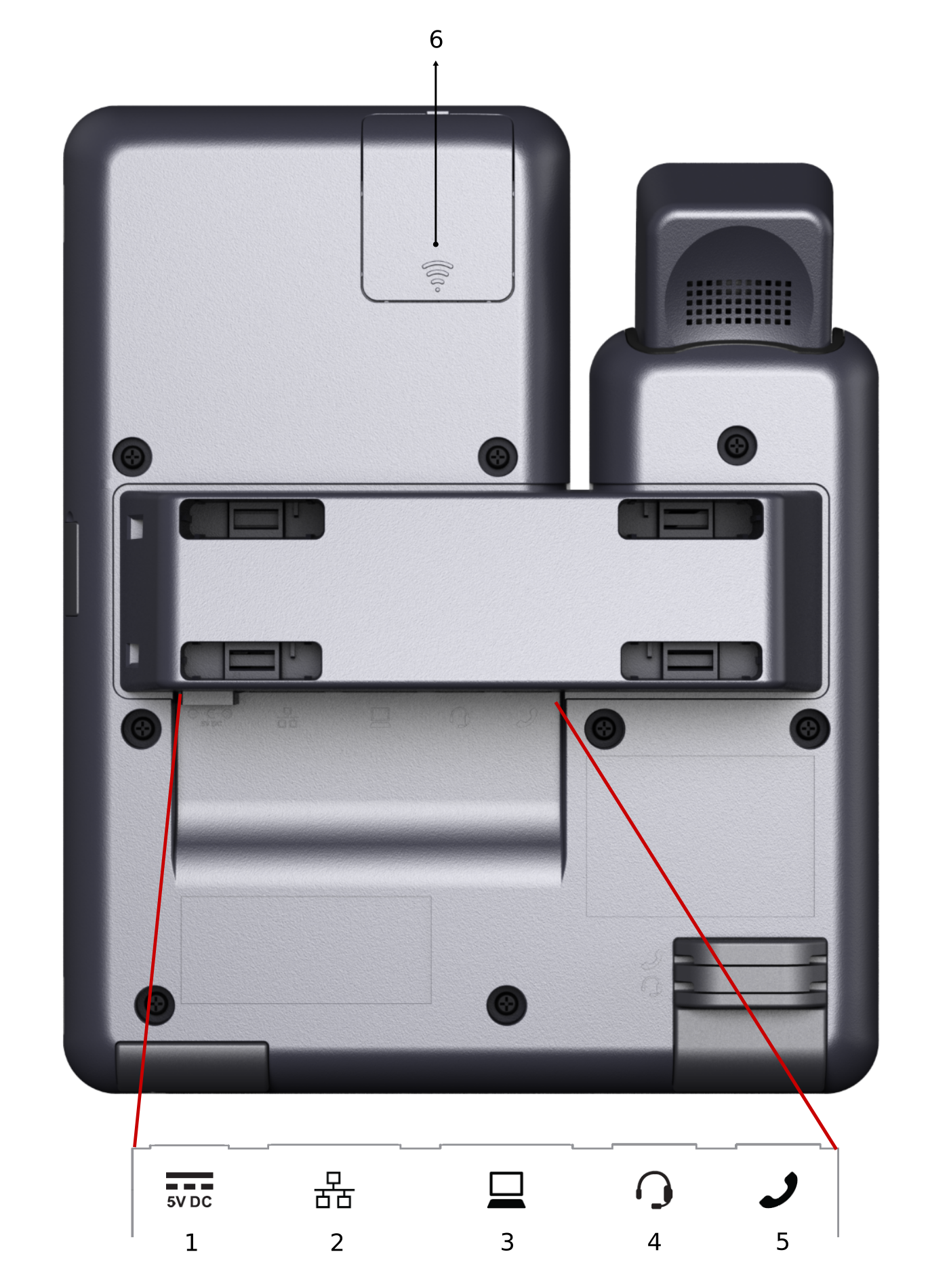
The following image illustrates the connection jacks that are present on the back panel of Avaya J169/J179 IP Phone.
The image schematically describes which device to connect to which jack.
|
No.
|
Name
|
Description
|
|---|---|---|
|
1
|
5V DC Jack
|
To connect the power supply.
|
|
2
|
Network port
|
To connect the Ethernet cable.
|
|
3
|
PC port
|
To connect the computer.
Note:
PC port is disabled when a Wi-Fi network is used.
|
|
4
|
Headset Jack
|
To connect the headset.
|
|
5
|
Handset Jack
|
To connect the handset.
|
|
6
|
WLAN Module Panel
|
To integrate the wireless module for Wi-Fi/Bluetooth support.
Note:
WLAN Module Panel is not provided in the Avaya J169 IP Phone.
|