

AVAYA DOCUMENTATION CENTER
Find answers to your technical questions and learn how to use our products
Avaya Session Border Controller Overview and Specification
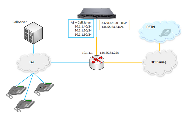
Avaya SBC connected to multiple subnets by using a single VLAN
In this scenario, Avaya SBC connects to a combination of VLAN and non-VLAN networks by using a single data interface.
Configuration details
-
Interfaces and purposes: In this scenario, only the A1 Avaya SBC data interface is used. This data interface provides connectivity to two different networks with the help of the next-hop router: the call server network and the ITSP network. Additionally, one of the networks, the ITSP network, is on a VLAN. Three Avaya SBC IP addresses are required for the call server network, one VLAN interface on the A1 physical interface, and one Avaya SBC IP address on the ITSP network.
-
Surrounding networking equipment: In this example, the next-hop router is configured to support two gateway IP addresses and one VLAN on the same physical port.
-
Network interfaces: The ITSP network requires VLAN tagging. The ITSP network uses VLAN ID (VID) 50. Packets leaving Avaya SBC on the ITSP network must contain a VID of 50. To enable VLAN tagging, create a VLAN interface. VLAN interfaces on Avaya SBC use the underlying facilities of a physical interface A1, A2, B1, or B2. Packets leaving and entering Avaya SBC on VLAN use the physical link connected to the associated physical interface. Define VLAN interface to connect Avaya SBC to the ITSP network. Use the Add VLAN button located in the Interfaces tab. Initially, keep the VLAN interface disabled. Then enable both the A1 and ITSP VLAN interfaces while other interfaces remain disabled.
-
Networks connected to Avaya SBC: In this example, the ITSP network connects to the VLAN interface on top of the physical A1 interface. Define the call server network in the same way as in other multiple subnet scenarios. Define the ITSP network and use the new VLAN interface.