AVAYA DOCUMENTATION CENTER
Find answers to your technical questions and learn how to use our products
IP Office Platform H.323 Telephone Installation
Example setup - Overview
The network is devised to allow the user PC to connect to the switch port of the IP Phone. A single cable then connects PC and IP Phone to the Ethernet Switch. For the purpose of this example, VLAN 100 is used for voice traffic and VLAN 101 is used for data traffic. The LAN1 interface of the IP Office control unit resides on the voice VLAN while the LAN2 interface resides in the data VLAN. Communication between the voice and data VLANs is facilitated by the IP Office control unit's router function.
HP-Switch - Configuration
Shown below are the web and CLI configuration output from the HP Procurve Switch. These were obtained using the configuration guidelines found below.
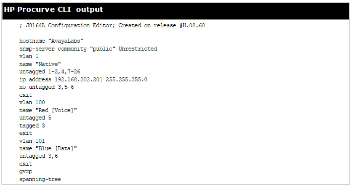
The table below summaries the HP configuration for ports and VLANs.
Port |
VLAN 100 Voice |
VLAN 101 Data |
Description |
|---|---|---|---|
3 |
Tagged |
Untagged |
This port was added to both VLAN 100 and VLAN 101.
Note:
When adding port 3 to VLAN 100 the Mode option must be tagged, but it must be untagged when adding to VLAN 101. |
5 |
Untagged |
- |
This port is included only in VLAN 100 and not included in VLAN 101. The Mode option must be set to Untagged for port 5 in this VLAN. |
6 |
- |
Untagged |
Port 6 is included only in VLAN 101 and not included in VLAN 100. The Mode option MUST be set to Untagged in this VLAN. |
The operation of this network is dependant on the functionality defined in HP documentation. Specifically, HP refers to this type of VLAN operation as Overlapping VLAN.