AVAYA DOCUMENTATION CENTER
Find answers to your technical questions and learn how to use our products
Installing the Avaya Solutions Platform 130 Series
Creating a virtual disk
About this task
Use this procedure to create a virtual disk by selecting the RAID level, physical disks, and virtual disk parameters.
Procedure
- Select Create Virtual Disk.
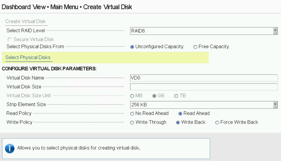
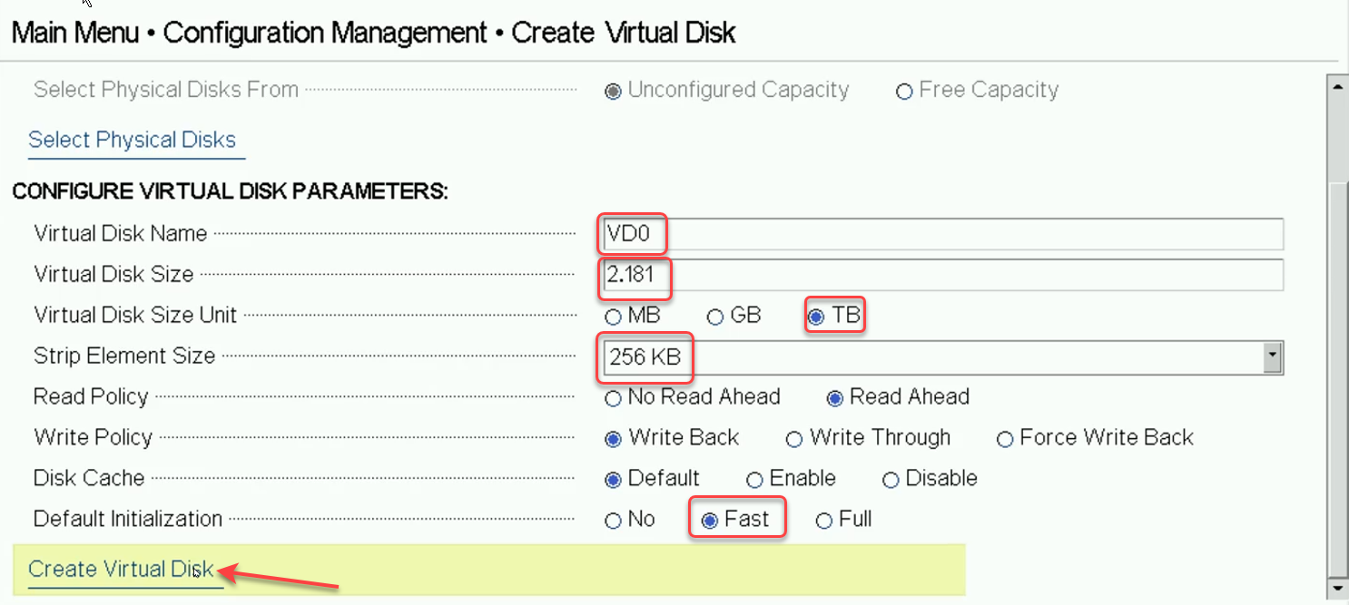
- Select the RAID level specified by the Avaya ASP 130 Profile configuration. ASP 130 P2 must be set for RAID 5. All other ASP 130 profiles must be set for RAID 6. Enter the Virtual Disk Name as VD0 and set the Strip Element Size to 256KB. Now scroll down and select Fast Default Initialization. Next press Select Physical Disks.
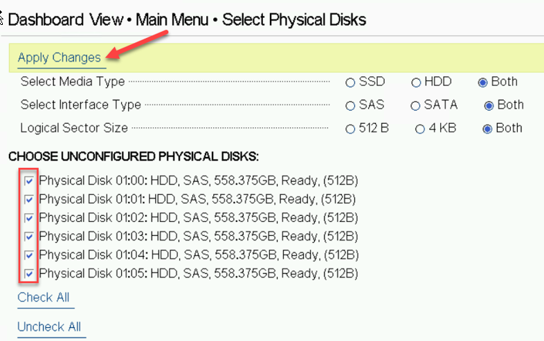
- The number of disks displayed should match the number of disks needed to build the ASP profile the user is creating. In the example above 6 HDDs are shown and must be selected to create an ASP 130 Profile 3, 4 or 5. Once the correct number of disks are verified and selected, click Apply Changes and then OK. Leave Media Types at their default settings. User will be moved back to the Create Virtual Disk Menu page.
- Select Virtual Disk Management.
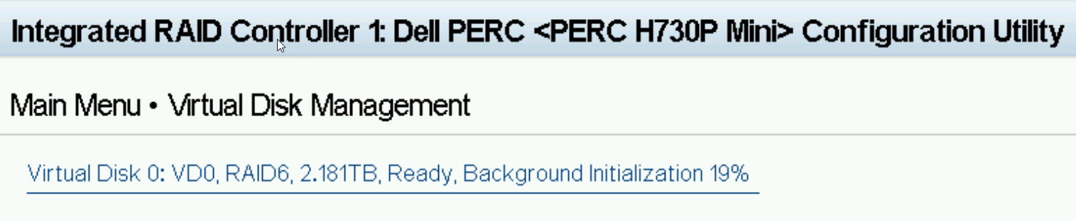
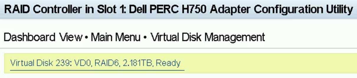
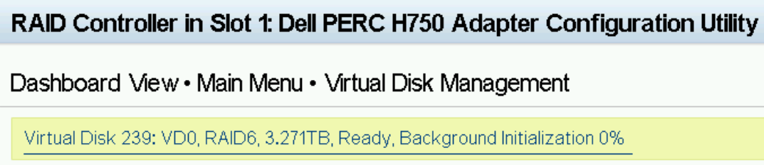
- The Virtual Disk is now displayed. Ready status will turn to Ready, Background Initialization xx% within 10 minutes of creation. Software installation can be performed during background initialization. Notice that the H730P Controller designates its first created disk as Virtual Disk 0; Whereas the H750 Controller designates its first created disk as Virtual Disk 239. This is expected behavior. The user defined Virtual Disk Name is still set to VD0 on both Controllers. Select BACK and then Finish/Finish to move back to the System Setup Main Menu.
Examples of the different ASP 130 Virtual Drives:
Figure : 1. ASP130 P2 with H730P RAID Controller
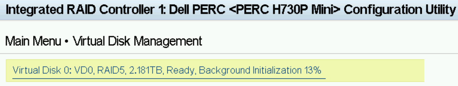
Figure : 2. ASP130 P2 with H750 RAID Controller
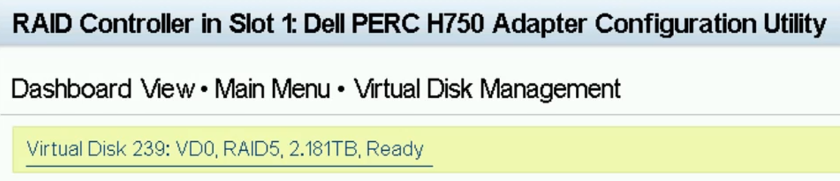
Figure : 3. ASP130 P3, P4 and P5 with H730P RAID Controller
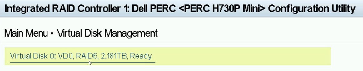
Figure : 4. ASP130 P3, P4 and P5 with H750 RAID Controller
Figure : 5. ASP 130 P51 with H730P RAID Controller
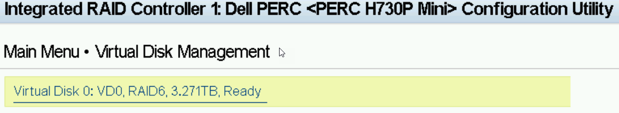
Figure : 6. ASP130 P51 with H750 RAID Controller
- Verify that Generic USB Boot and Hard-disk Drive Placeholder are set to Enabled and then select UEFI Boot Settings.
Figure : 7. R640 ASP130 with H730P RAID Controller
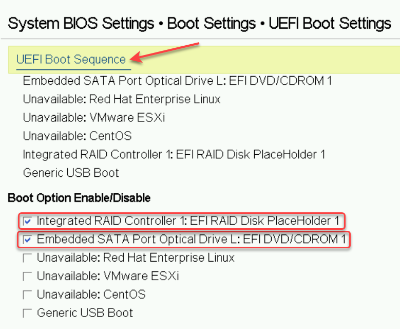
Figure : 8. R640 ASP130 with H750 RAID Controller
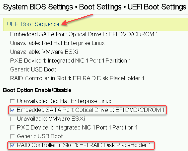
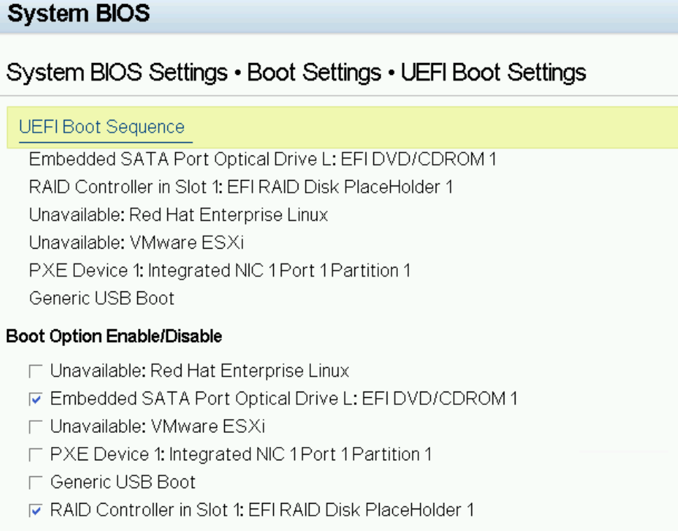
- When on this page confirm or change the Boot Option Enable/Disable so that only the Embedded SATA Port Optical L: EFI DVD/CDROM 1 and the RAID Controller (1) or (in Slot 1): EFI RAID Disk PlaceHolder 1 are set to Enabled (checked). All other options can be ignored. Now click the UEFI Boot Sequence link. A Change Order pop-up window will display.
Figure : 9. R640 ASP130 with H730P RAID Controller
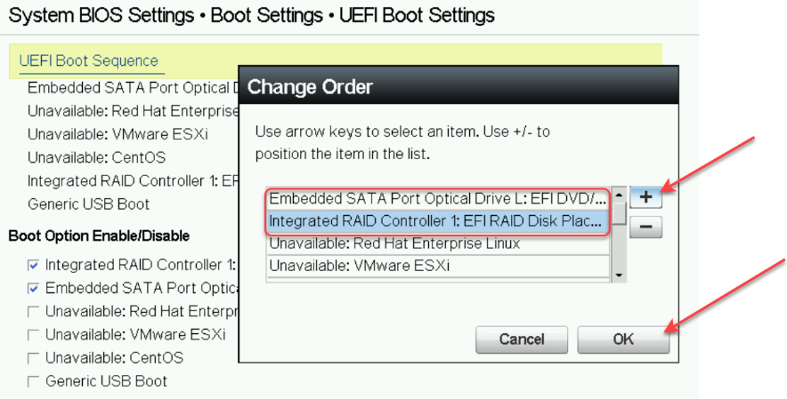
Figure : 10. R640 ASP130 with H750 RAID Controller
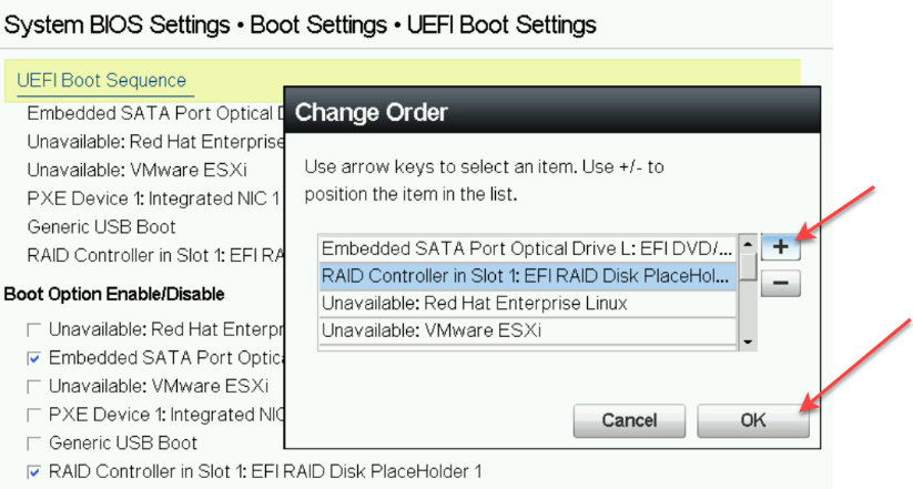
- In the pop-up window select the enabled Boot Option devices and move them to the top of the UEFI Boot Sequence as shown. Select the Boot device to be moved and then click the “+” to move the device up in the boot sequence. Place the Embedded SATA Port Optical L: EFI DVD/CDROM 1 first in the boot sequence followed by the RAID Controller (1) or (in Slot 1): EFI RAID Disk PlaceHolder 1 as shown above. All other boot place holders can be ignored. When the two aforementioned devices have been placed in the proper boot sequence click OK.
Figure : 11. R640 ASP130 with H730P RAID Controller
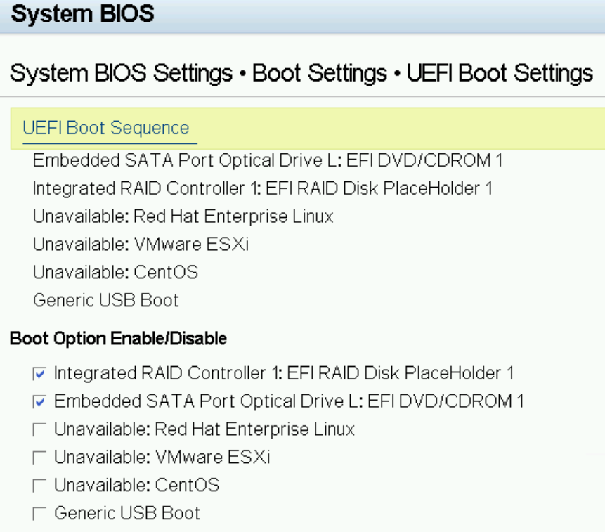
Figure : 12. R640 ASP130 with H750 RAID Controller
Next Steps
ASP 130 R6.0.x (KVM on RHEL 8.10) software installation can now proceed.