AVAYA DOCUMENTATION CENTER
Find answers to your technical questions and learn how to use our products
Installing the Avaya Solutions Platform 130 Series
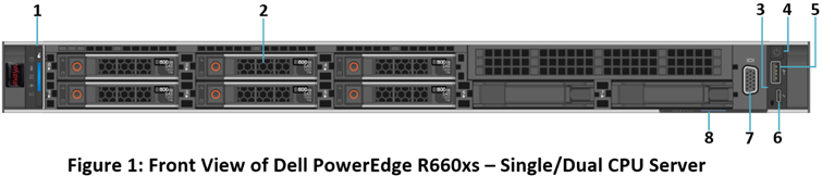
Front view of Dell™ PowerEdge™ R660xs Server
Note:
The Dell R660xs does not contain a CD-ROM drive. All media installation is done using USB.
No. |
Item |
Icon |
Description |
|---|---|---|---|
1 |
Left control panel |
NA |
Displays the system health, system ID, and status LED indicators.
|
2 |
Drive slots |
N/A |
Enables installation of hard disk drives (HDDs) that are supported on your system. |
3 |
Right control panel |
NA |
Contains the power button, USB port, iDRAC Direct micro port, and the iDRAC Direct status LED. |
4 |
Power button |

|
Indicates if the system is powered on or off. Press the power button to manually power on or off the system.
Note:
Press the power button to gracefully shut down an ACPI-compliant operating system. |
5 |
USB 2.0 port |

|
The USB is a 4-pin connector and 2.0-compliant. This port enables you to connect USB devices to the system. |
6 |
iDRAC Direct micro port |
 |
The iDRAC Direct port (Micro-AB USB) enables you to access the iDRAC direct features. |
7 |
VGA port |
 |
Enables connection to the display device (console) of the system. If the user connects to the front VGA port, the rear VGA port does not function. |
8 |
Express service tag |
NA |
The Express Service Tag is a slide-out label panel that contains system information such as Service Tag, NIC, MAC address, and so on. If you have opted for the secure default access to iDRAC, the Information tag will also contain the iDRAC secure default password. |