AVAYA DOCUMENTATION CENTER
Find answers to your technical questions and learn how to use our products
Deploying and Upgrading Avaya G430 Branch Gateway
Removing the G430 cover
About this task
Voltage:
Disconnect the G430 gateway from the external power source before proceeding.
Electrostatic discharge alert
Do not touch any components on the printed circuit board.
Procedure
- Lift the cover off the G430 gateway.
Figure : 1. Removing the G430 cover screw from the top of the device 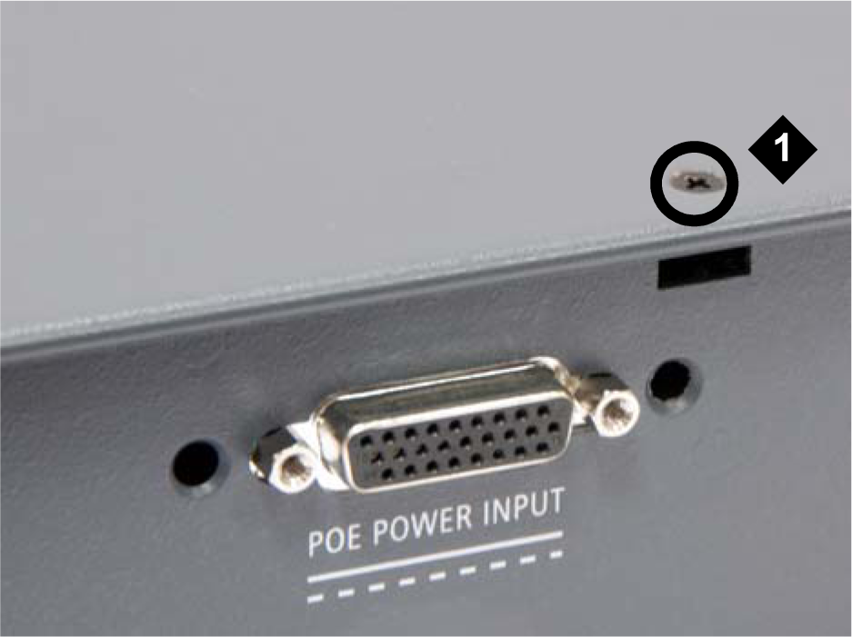 Note:
Note:POE POWER INPUT connector is not present in G430 (v2 or v3).
Table 1: Figure notes: G430 top cover screw
Figure : 2. Removing G430 cover screws from the right side 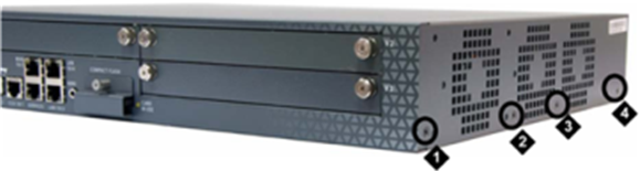
Table 2: Figure notes: G430 right-side cover screw
G430 right-side cover screw
G430 right-side cover screw
G430 right-side cover screw
Figure : 3. Removing G430 cover screws from the left side 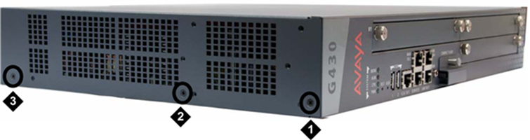
Table 3: Figure notes: G430 left-side cover screw
G430 left-side cover screw
G430 left-side cover screw