AVAYA DOCUMENTATION CENTER
Find answers to your technical questions and learn how to use our products
Installing the Avaya Solutions Platform 130 Series
Administering NIC Bonding in KVM on RHEL 9.6
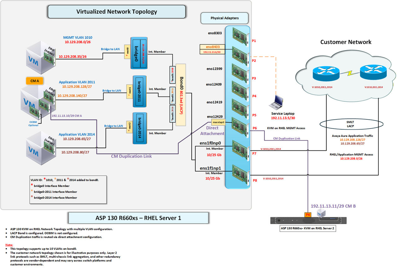
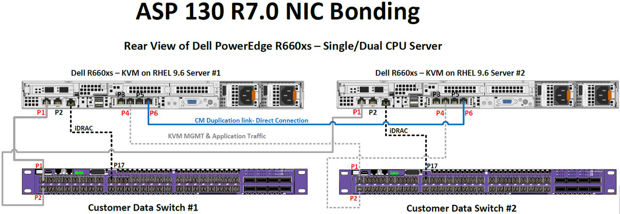
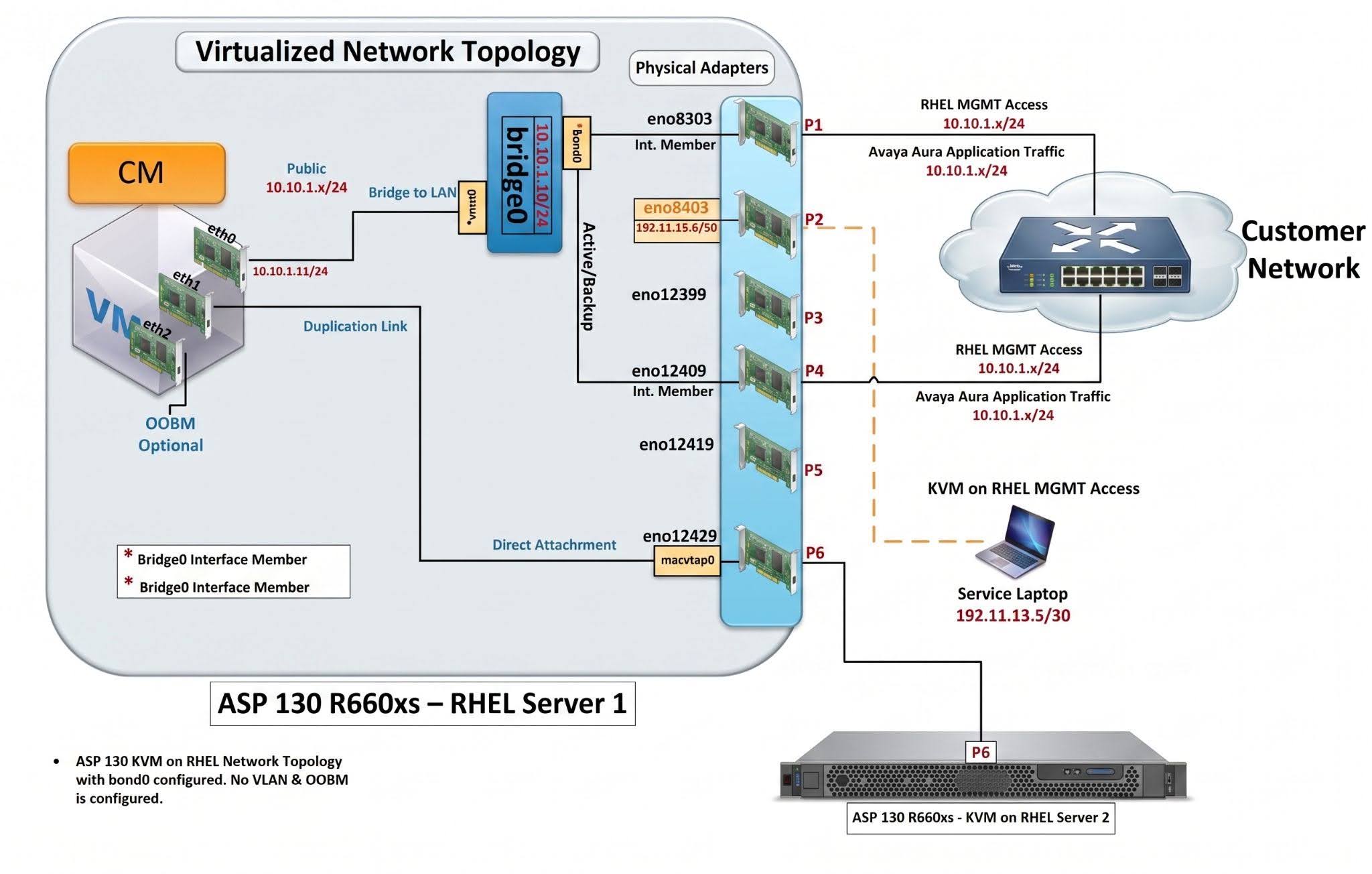
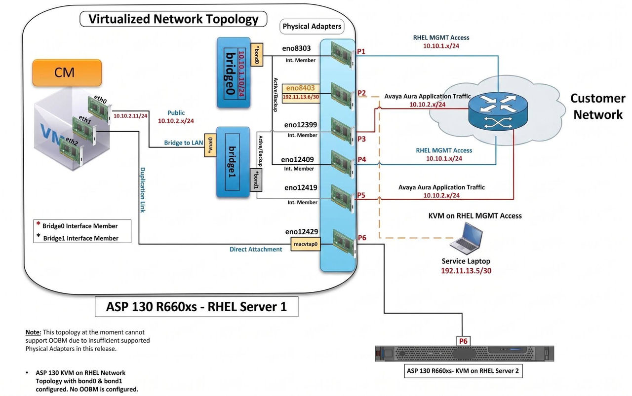
Red Hat Enterprise Linux (RHEL) offers a variety of options and configurations for setting up network bonding. While the Red Hat vendor does not provide a single "best" recommended configuration, it is important to note that for Avaya ASP 130 R7.x, the only tested and supported configuration method is adding a bond with physical interfaces. Be aware that combining bridges, bridges with VLAN tags, or virtual machine interfaces when adding a bond is not supported by Avaya. When applicable to keep a streamlined and consistent behavior the default bridge0 will be the primary reference point for NIC bonding behaviors and expectations.
Note:
The data switch ports listed in the following table are for demonstration purposes and are intended to serve as a reference only.
|
Server NIC
|
R660xs Hypervisor
|
Data Switch 1
|
Data Switch 2
|
Usage
|
Native VLAN
|
|
|---|---|---|---|---|---|---|
|
Server #1
|
P1
|
eno8303
|
P1
|
-
|
KVM MGMT & Application Traffic
|
MGMT & VoIP VLAN
|
|
Server #1
|
P4
|
eno12409
|
-
|
P1
|
KVM MGMT & Application Traffic
|
MGMT & VoIP VLAN
|
|
Server #1
|
iDRAC
|
N/A
|
P17
|
-
|
Dell iDRAC Interface
|
MGMT VLAN
|
|
Server #2
|
P1
|
eno8303
|
P2
|
-
|
KVM MGMT & Application Traffic
|
MGMT & VoIP VLAN
|
|
Server #2
|
P4
|
eno12409
|
-
|
P2
|
KVM MGMT & Application Traffic
|
MGMT & VoIP VLAN
|
|
Server #2
|
iDRAC
|
N/A
|
---
|
P17
|
Dell iDRAC Interface
|
MGMT VLAN
|
Note:
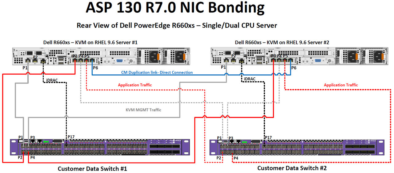
The data switch ports listed in the following table are for demonstration purposes and are intended to serve as a reference only.
|
Server NIC
|
R660xs Hypervisor
|
Data Switch 1
|
Data Switch 2
|
Usage
|
Native VLAN
|
|
|---|---|---|---|---|---|---|
|
Server #1
|
P1
|
eno8303
|
P1
|
-
|
KVM MGMT Traffic
|
MGMT VLAN
|
|
Server #1
|
P4
|
eno12409
|
-
|
P1
|
KVM MGMT Traffic
|
MGMT VLAN
|
|
Server #1
|
P3
|
eno12399
|
P2
|
-
|
Application Traffic
|
VoIP VLAN
|
|
Server #1
|
P5
|
eno12419
|
-
|
P2
|
Application Traffic
|
VoIP VLAN
|
|
Server #1
|
iDRAC
|
N/A
|
P17
|
-
|
Dell iDRAC Interface
|
MGMT VLAN
|
|
Server #2
|
P1
|
eno8303
|
P3
|
-
|
KVM MGMT Traffic
|
MGMT VLAN
|
|
Server #2
|
P4
|
eno12409
|
-
|
P3
|
KVM MGMT Traffic
|
MGMT VLAN
|
|
Server #2
|
P3
|
eno12399
|
P4
|
-
|
Application Traffic
|
VoIP VLAN
|
|
Server #2
|
P5
|
eno12419
|
-
|
P4
|
Application Traffic
|
VoIP VLAN
|
|
Server #2
|
iDRAC
|
N/A
|
-
|
P17
|
Dell iDRAC Interface
|
MGMT VLAN
|
Note:
The data switch ports listed in the following table are for demonstration purposes and are intended to serve as a reference only.
|
Server NIC
|
R660xs Hypervisor
|
Data Switch 1
|
Data Switch 2
|
Usage
|
Native VLAN
|
|
|---|---|---|---|---|---|---|
|
Server #1
|
P7
|
ens1f0np0
|
P1
|
-
|
KVM & Application Traffic
|
MGMT VLAN
|
|
Server #1
|
P8
|
ens1f1np1
|
-
|
P1
|
KVM & Application Traffic
|
MGMT VLAN
|
|
Server #1
|
iDRAC
|
N/A
|
P17
|
-
|
Dell iDRAC Interface
|
MGMT VLAN
|
|
Server #2
|
P7
|
ens1f0np0
|
P2
|
-
|
KVM & Application Traffic
|
MGMT VLAN
|
|
Server #2
|
P8
|
ens1f1np1
|
-
|
P2
|
KVM & Application Traffic
|
MGMT VLAN
|
|
Server #2
|
iDRAC
|
N/A
|
-
|
P17
|
KVM & Application Traffic
|
MGMT VLAN
|
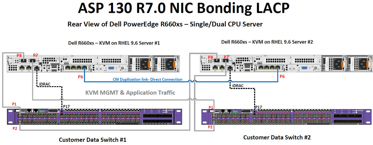
Note:
This topology includes VLANs to logically segregate different types of traffic over a single network trunk. While VLANs are not required for LACP, their use is recommended when multiple traffic flows share the same link.