

AVAYA DOCUMENTATION CENTER
Find answers to your technical questions and learn how to use our products
Installing the Avaya Solutions Platform 130 Series
Installing the Dell R660xs server
Use this procedure to install the server using the provided rail kit. The following procedure is a copy of the Dell rail installation instructions that accompany the Avaya Dell R660xs packaging. This information is intended to instruct the user on how to install the rail kit into a rack and how to connect power and network cables. The server depicted in these drawings is a generic server drawing. For specific ASP 130 port designations, refer to figures 2 and 3 of Rear view of Dell™ PowerEdge™ R660xs Server of this document.
Before you begin
Warning:
-
Before you begin, read and follow the safety instructions in your Enterprise Products Safety, Environmental and Regulatory Information Booklet shipped with your system.
-
Reference the Rail Installation Guide shipped with the rail kit. This may have updated instructions that supersede this document.
-
To avoid injury, do not attempt to lift the system by yourself.
-
Verify that the rack is installed according to the manufacturer's instructions and in accordance with all local codes and laws. Verify that the rack is grounded in accordance with local electrical code.
Note:
-
Avaya customers are required to have a VGA monitor, USB keyboard, and USB mouse (optional) available for use by installation and servicing technicians.
-
This rail kit is compatible with square, unthreaded round, and threaded round hole racks.
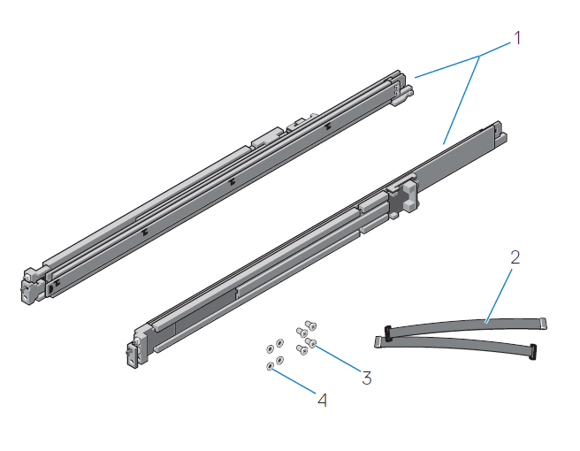
- Identify and separate the components of the sliding rail assembly kit.
ADDITIONAL INFORMATION:
-
Two sliding rail assemblies — (1)
-
Two velcro straps — (2)
-
Four screws — (3)
-
Four washers — (4)
-
- Place the kit components within easy reach of your work area.
- Perform the following actions to install the left and right rails, beginning with the left rail:
ADDITIONAL INFORMATION:
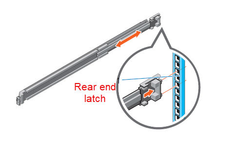
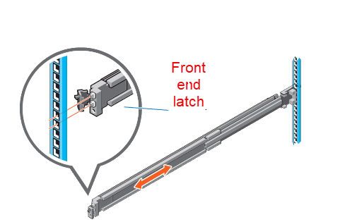 Task orderTask1Fully extend the rear sliding bracket of the rail so that the rail is as long as possible.2Position the rail end piece labeled FRONT facing inward and orient the rear end piece to align with the holes on the rear rack flanges.3Push the rail straight toward the rear of the rack until the latch locks into place.4For the front end piece, rotate the latch outward and pull the rail forward until the pins slide into the flange, and release the latch to secure the rail in place.5Repeat the preceding steps to install the right rail.
- Perform the following actions to install the system in the rack:
ADDITIONAL INFORMATION:
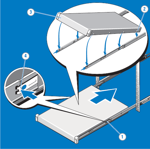 Task orderTask1Pull the inner slide rails out of the rack until they lock into place.2Locate the rear rail standoff on each side of the system and lower them into the rear J-slots on the slide assemblies.3Rotate the system downward until all the rail standoffs are seated in the J-slots.4Push the system inward until the lock levers click into place. Press the slide-release lock buttons on both rails and slide the system into the rack
- To secure the rails to the rack for shipping or in an unstable environment, install the supplied screws to the rails. For square hole racks, install the supplied conical washer to the screw before installing the screw. For unthreaded round hole racks, install only the screw without the conical washer.