

AVAYA DOCUMENTATION CENTER
Find answers to your technical questions and learn how to use our products
Installing the Avaya Solutions Platform 130 Series
Creating a virtual disk
Follow this procedure to initialize a new virtual disk by selecting the appropriate RAID level, physical drives, and virtual disk parameters.
- When hardware boot screen appears, select <F2> System Setup.
- From the System Setup Main Menu, select Device Settings.
- Select the RAID Controller listed at the top of the menu to access its configuration.
- From the RAID Controller Dashboard View, select Main Menu and go to Configuration Management.
- Select Create Virtual Disk.
ADDITIONAL INFORMATION:
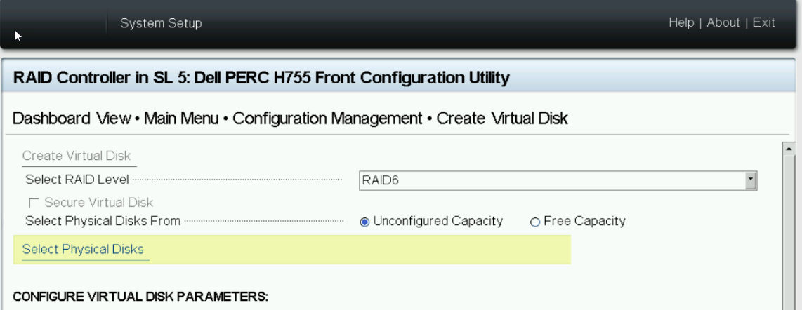
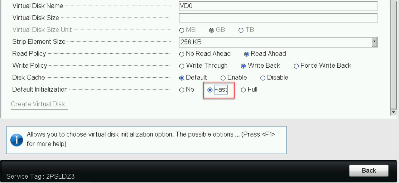
- On the Create Virtual Disk screen, select the RAID level specified by the target Avaya ASP profile. RAID level is RAID6 for A2, A3 and A31 profiles or RAID5 for A1 profiles. Enter the Virtual Disk Name as VD0 and set the Strip Element Size to 256KB. Now scroll down and select Fast Default Initialization. Next select Select Physical Disks.
ADDITIONAL INFORMATION:
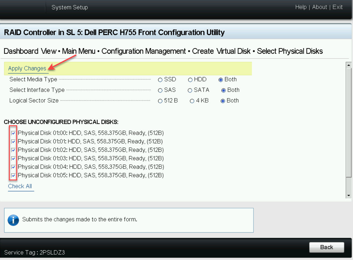
- The number of disks displayed should match the number of disks needed to build the target ASP profile. In the example above, 6 HDDs are selected (applicable to Profiles A2 and A3). Leave Media Types at their default settings. Select . You return to the Create Virtual Disk Menu page.
ADDITIONAL INFORMATION:For more information on disk selection and virtual disk sizes see ASP 130 Data Storage Capacity table below.RAID ConfigurationRaw StorageUsable Capacity in TerabytesUsable Capacity in Tebibytes1ASP 130Profile55x600GB = 3.0TB2.42.181A166x600GB = 3.6TB2.42.181A266x600GB = 3.6TB2.42.181A368x600GB = 4.8TB3.63.271A3155x1.2TB = 6.0TB4.84.364A166x1.2TB = 7.2TB4.84.364A266x1.2TB = 7.2TB4.84.364A368x1.2TB = 9.6TB7.26.546A31This table provides the usable capacity in Gibibytes and Tebibytes in addition to Gigabytes and Terabytes, as operating systems may calculate data storage space in this way.
- Ensure the number of displayed disks corresponds to the requirements of the target ASP 130 profile. For instance, creating an ASP 130 Profile A2 or A3 requires the selection of six (6) HDDs. After verifying the disk selection, click to return to the Create Virtual Disk menu.
ADDITIONAL INFORMATION:
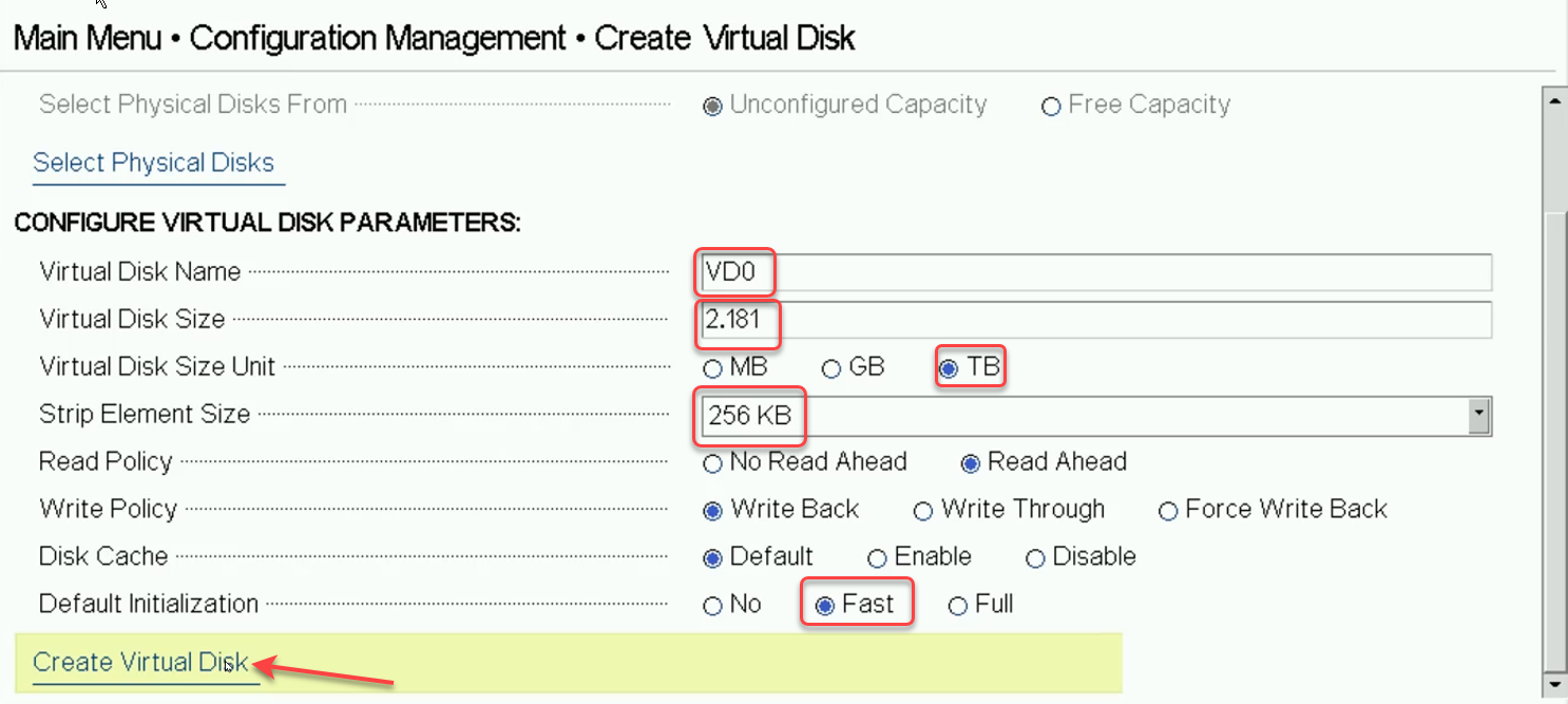
- Notice that the Virtual Disk Size is now populated to reflect its number and size of HDDs and RAID array type. ASP 130 profiles A1, A2 and A3 should show a size of 2.181TB. ASP 130 profile A31 should show a size of 3.271TB. Once values are confirmed select Create Virtual Disk then select . Next, select and see that a new virtual disk has been created. The controller enumerates the first created Virtual Disk as 239.
ADDITIONAL INFORMATION:
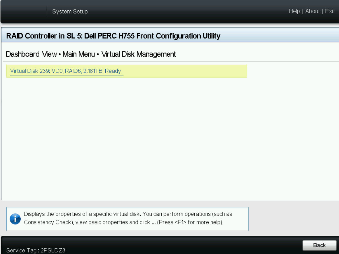
- The Virtual Disk is now displayed. Ready status will turn to Ready, Background Initialization xx% within 10 minutes of creation. Software installation can be performed during background initialization. Select to move back to the System Setup Main Menu.
- From the System Setup Main Menu, select System BIOS.
- Select Boot Settings.
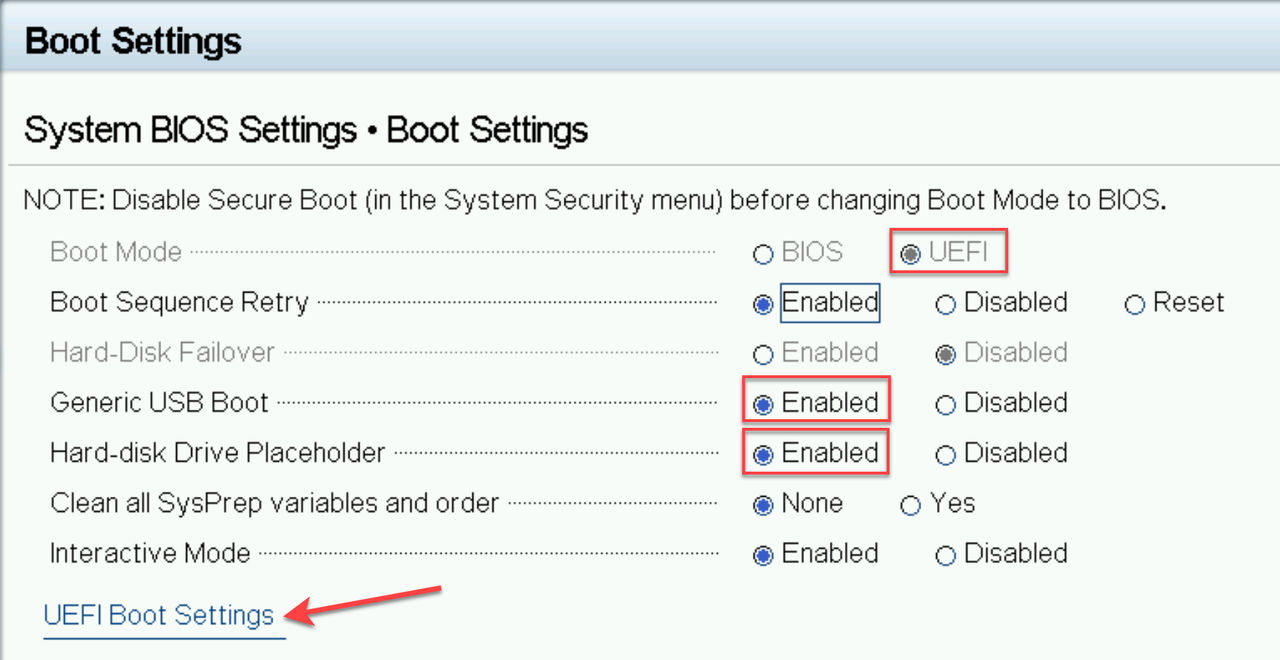
- Set Generic USB Boot and Hard-disk Drive Placeholder to Enabled and then select Back.
- Select to save the settings changes just made. The server must reboot to rescan boot setting changes. Click to reboot the server. The server will now reboot.
- When the hardware boot screen appears, press <F2> to enter System Setup.
- From the System Setup Main Menu, select Device Settings.
- Select System BIOS.
- Select Boot Settings.
- Verify that the Boot Mode is set to UEFI. Verify that Generic USB Boot and Hard-disk Drive Placeholder are set to Enabled and then select UEFI Boot Settings.
ADDITIONAL INFORMATION:
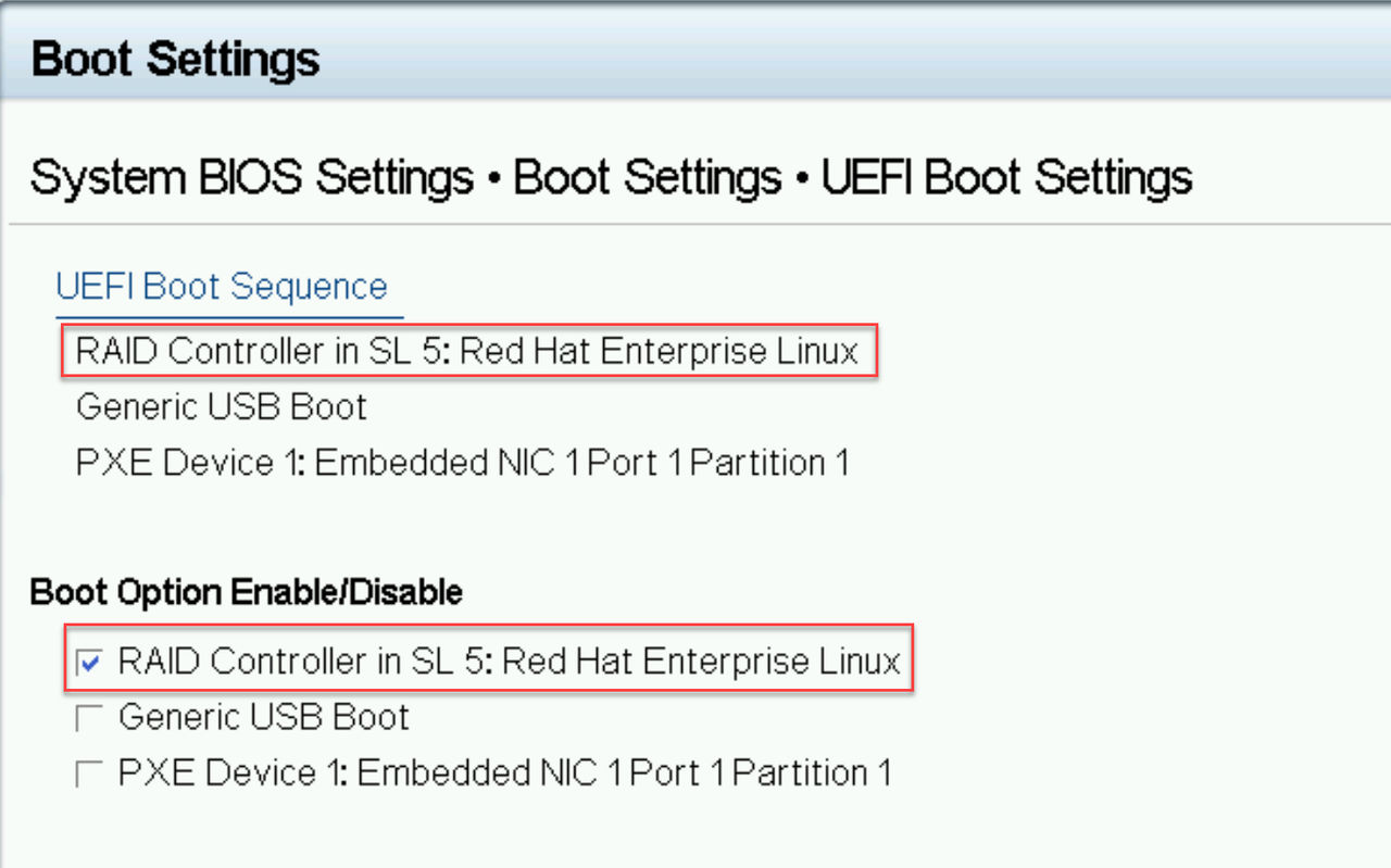
- Confirm or change the Boot Option Enable/Disable so that only the Generic USB Boot and the RAID Controller in SL 5: Red Hat Enterprise Linux or EFI RAID Disk Placeholder - Disk 239 (whichever is displayed) are checked/enabled. If an operating system has not been installed on the system, the generic Hard-disk Drive Placeholder name, RAID Controller in SL 5: EFI RAID Disk Placeholder - Disk 239 is displayed. All other options can be ignored. Now click the UEFI Boot Sequence link. A Change Order pop-up window will display.
ADDITIONAL INFORMATION:
- In the pop-up window select the enabled Boot Option devices and move them to the top of the UEFI Boot Sequence as shown. Select the Boot device to be moved and then click the “+” to move the device up in the boot sequence. Place the Generic USB Boot first in the boot sequence followed by the RAID Controller in SL 5: Red Hat Enterprise Linux or EFI RAID Disk Placeholder - Disk 239 (whichever is displayed). All other boot place holders can be ignored. When the two aforementioned devices have been placed in the proper boot sequence click OK.
ADDITIONAL INFORMATION:
- Confirm that the UEFI Boot Sequence has the Generic USB Boot first in the boot sequence followed by the RAID Controller in SL 5: Red Hat Enterprise Linux or EFI RAID Disk Placeholder - Disk 239 (whichever is displayed). Also confirm that the only devices that are enabled under the Boot Option Enable/Disable heading are the Generic USB Boot and the RAID Controller in SL 5: Red Hat Enterprise Linux or EFI RAID Disk Placeholder - Disk 239 (whichever is displayed). Once confirmed select Back twice to move to the System BIOS Settings screen.
- Click to save System BIOS Settings changes.
- Click to exit and reboot the server.
Next steps
Server RAID configuration is now complete. The created Virtual Drive is now ready and available for ASP 130 R7.x (KVM on RHEL 9.6) software installation.
Go to Performing server recovery and/or software remastering for information on installation of KVM on Red Hat Enterprise Linux Software.