

AVAYA DOCUMENTATION CENTER
Find answers to your technical questions and learn how to use our products
Installing the Avaya Solutions Platform 130 Series
Configuring a VLAN ID on a new bridge using the network script
Putting VoIP and Data on separate networks is a recommended best practice and industry standard. Isolating VoIP traffic from Data/Management Traffic helps to enhance network security and enables customers to implement QoS adequately. It also helps by simplifying network traffic management and troubleshooting as each network can be monitored independently. By independently monitoring each network, a network administrator can quickly identify and address issues specific to either VoIP or data/management services, improving response times and minimizing downtime.
Note:
Call signaling in VoIP communications, whether directed to Communication Manager (CM), Session Manager (SM), or media servers, is still classified as VoIP traffic, even if media (RTP packets) is not transmitted as part of the call signaling process.
Before you begin
-
It is expected to have at least one extra physical interface apart from the one designated for the Hypervisor management interface (eno8303).
-
Connect the designated server port (for example, eno12419) to the customer’s data switch. For a network topology illustration of this configuration, refer to VLAN configuration on separate bridges in an ASP 130 R7.x – Hypervisor Layer.
-
Customer data switch port connecting server must be already configured with the corresponding VLAN ID and VLAN tagging (IEEE 802.1Q) enabled.
Note:
In the event of a misconfiguration with the primary interface (bridge0), the server will only be accessible through the services port.
- Connect to the ASP host using the services port connection.
- Log in to the ASP host by using a Secure Shell (SSH) client e.g., PuTTY.
- Authenticate using the existing custadm credentials or craft if EASG is enabled.
- Execute the following CLI command: configNetwork.
- Follow the script prompts:
- Type y to continue if the connection is via services port.
- Type n to continue (OOBM configuration is not part of this procedure).
ADDITIONAL INFORMATION:Note:The network script automatically detects if OOBM has been previously configured on the management interface. If OOBM is found, the script will display a "Y" by default. To retain the current OOBM configuration, simply press Enter without making any changes to keep the existing OOBM configuration intact.
- Type n to continue. Configuring OOBM bridge for VM use configuration is not part of this procedure.
- Enter the number of bridges to configure <1-2>. In this example, type 2 to get a second bridge configured.
- In the 'Select configuration for bridge0', type 0.
ADDITIONAL INFORMATION:In this example no changes will be made to bridge0, therefore 1G direct interface will be left configured.
- Type y to configure a Management/VM's VLAN.
- Enter a value <1-4094> for the Management/VM's VLAN ID. For example, 1010.
ADDITIONAL INFORMATION:Note:Some network switch vendors may support only a subset of the IEEE 802.1Q valid VLAN ID range (1–4094). Therefore, verify that the VLAN ID entered is supported by the customer’s data switch before applying any changes.
- Type n to continue. In this example a single VLAN will be configured on bridge0.
- Select the desired configuration for bridge1 (Secondary VM Bridge). In this example, type 0 for a 1G direct interface. However, a bond can also be configured if required.
ADDITIONAL INFORMATION:Note:The network script automatically detects current configuration. If bridge1 has been previously configured, current configuration will be displayed in parenthesis e.g (0) for 1GB direct interface. To retain the current configuration, simply press Enter without making any changes to keep the existing configuration intact.
- From the list of available 1G ports, enter the port number to use for the bridge1 direct interface. In this example, type 0 to select eno12409.
- To configure VLANs on the bridge1 ports, type y.
ADDITIONAL INFORMATION:Note:The network script automatically detects current configuration. If bridge1 has been previously configured with 1 or more VLANs, these will be displayed e.g. Current VLANs: 2011
- Enter 1 to 5 VLAN IDs separated by spaces. Enter a value <1-4094>, for example 2011.
ADDITIONAL INFORMATION:Note:Some network switch vendors may support only a subset of the IEEE 802.1Q valid VLAN ID range (1–4094). Therefore, verify that the VLAN ID entered is supported by the customer’s data switch before applying any changes.In this example, a single VLAN will be configured on a second bridge, bridge1, however, multiple VLANs (VLAN trunking) can be configured as well.At this stage, the script will prompt the user to begin configuring a bridge for each VLAN ID entered in the previous step. In this example, one bridge will be created for VLAN ID 2011.The configNetwork script automatically assigns a default label to each new bridge including the VLAN ID. If changing the default label, it is strongly recommended to configure these labels in a way that is easy to identify, for example: VoIP-2011, Management-1010, etc.
- Enter the name of the bridge associated with the VLAN configured in the previous step. The script assigns a default name (e.g., bridge1-2011). Press Enter to accept the default value, or enter a different name.
ADDITIONAL INFORMATION:Other:Bridge name must be unique. Do NOT assign the same name to multiple bridges.Note:Bridge labels must be between 2 and 15 characters in length and must contain only alphanumeric characters, a dash (-), or an underscore (_).
- Press Enter key (7 times) until prompt displays Continue with these values? y=continue/n=retry/q=quit (n). If satisfied with current selections type y.
ADDITIONAL INFORMATION:Note:Although multiple changes at the same time are supported by the network script, IP address changes are not part of this procedure.
[custadm@asp130-r660xs-20841 ~]$ configNetwork
 ===================  Server Network Configuration  ===================
 Note: you should run this command from the console or services port
       After making configuration changes running VMs should be restarted.

 Do you want to continue (y/n) y

 The configured or default value is displayed in parentheses ().
 Press 'enter' to accept it, enter 'd' to delete it or type a new value.

 Connect this server to an Out Of Band Management network (OOBM)? y/n (n) n
 Create an OOBM bridge for VMs use? y/n (n) n

 ========== Network Bridge Configuration ==========
 Configure network bridges for management and VMs.

 Do you want to configure 1 or 2 bridges? (1) 2

  === Configuring bridge0 (Management/VM Bridge) ===
  0) 1G direct interface
  1) 1G active/backup bond
  2) 10/25G direct interface
  3) 10/25G LACP bond
  4) 10/25G active/backup bond

 Select configuration for bridge0: (0) 0
 Selected: 1G direct interface for bridge0
 Using management port: eno8303
 Do you want to configure a Management/VM's VLAN? y/n (n) y
 Enter the Management/VM's VLAN ID (): 1010
 Configure additional VLANs on the bridge0 (Management/VM's) ports? y/n (n) n

  === Configuring bridge1 (Secondary VM Bridge) ===
  0) 1G direct interface
  1) 1G active/backup bond
  2) 10/25G direct interface
  3) 10/25G LACP bond
  4) 10/25G active/backup bond
  5) No second bridge

 Select configuration for bridge1: (5) 0
 Selected: 1G direct interface for bridge1
 Available 1G ports:
  0) eno12409
  1) eno12419
  2) eno12429
  3) eno12399
 Enter the port # to use for direct connection: 0
 Selected port: eno12409

 Configure VLANs on the bridge1 ports? y/n (n) y
 Enter 1 to 5 VLAN IDs separated by spaces (q=none): 2011
 Enter the name of the bridge to connect to VLAN 2011 (bridge1-2011):
 Enter Server hostname (asp130-r660xs-20841.acp.avaya.com):
 Enter Server IPv4 (192.168.208.41):
 Enter Server netmask or /prefix (/26):
 Enter the IPv4 default gateway (192.168.208.1):
 Do you want to configure IPv6? y/n (n)
 Enter comma separated DNS servers (198.152.8.11):
 Enter comma separated IPv4 domain search (acp.avaya.com):
 Continue with these values? y=continue/n=retry/q=quit (n) y

  Bridge bridge0: initialization successful
 Bridge slave port eno8303.1010 on bridge0: initialization successful
 Bridge bridge1: initialization successful
 Bridge slave port eno12409 on bridge1: initialization successful
 Add bridge1-2011 on bridge1-2011-port VLAN=2011
 Bridge bridge1-2011: initialization successful
 VLAN 2011 on bridge1-2011-port initialization successful
 Bridge bridge0: IP initialization successful.
Next steps
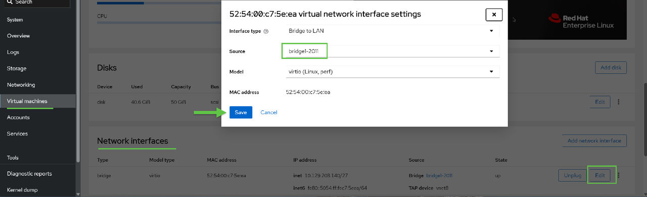
Migrate the Avaya application virtual network interfaces to the appropriate newly created bridge.
Note:
Virtual machines must be powered off before making any network changes.
When segregating networks, a new network segment for VoIP will be provisioned. Coordinate with the customer’s network administrators to ensure that Avaya Aura applications are re-IP’ed accordingly.