AVAYA DOCUMENTATION CENTER
Find answers to your technical questions and learn how to use our products
Maintenance Procedures for Communication Manager, Branch Gateways and Servers
Open Systems Interconnection model
The Open Systems Interconnection (OSI) model for data communications contains seven layers, each with a specific function. In the OSI model, data communication uses only Layers 1 and 2 of the model.
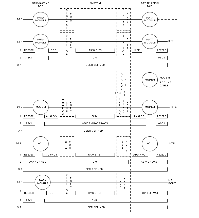
Layer 1, or the physical layer, covers the physical interface between devices and the rules, by which bits are passed. Among the physical layer protocols are RS-232, RS-449, X.21, DCP, DS1, and others.
Layer 2, or the data-link layer, refers to code created and interpreted by the DCE. The originating equipment can send blocks of data with the necessary codes for synchronization, error control, or flow control. With these codes, the destination equipment checks the physical link’s reliability, corrects any transmission errors, and maintains the link. When a transmission reaches the destination equipment, it strips any Layer 2 information the originating equipment may have inserted. The destination equipment passes to the destination DTE equipment only the information sent by the originating DTE equipment. The originating DTE equipment can also add Layer-2 code to be analyzed by the destination DTE equipment. The DCE equipment treats this layer as data and passes it along to the destination DTE equipment as it would any other binary bits.
Layers 3 to 7 (and the DTE-created Layer 2) are embedded in the transmission stream and are meaningful only at the destination DTE equipment. Therefore, they are shown in the figure as user-defined, with no state changes until the transmission stream reaches its destination.
Figure : 1. Intra-port and Inter-port data transmission states