AVAYA DOCUMENTATION CENTER
Find answers to your technical questions and learn how to use our products
Administering Avaya G430 Branch Gateway
GRE tunnel application example
This section provides an example of a GRE tunnel application and its configuration.
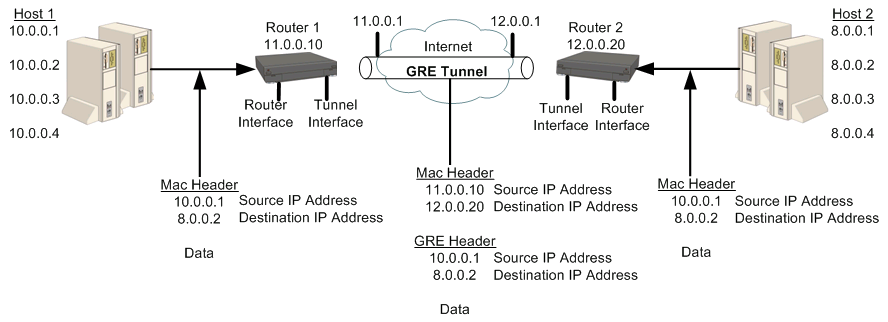
In the example shown in this figure, Host 1 and Host 2 are private networks using a GRE tunnel to connect them via the Internet. 11.0.0.10 and 12.0.0.20 are public IP addresses used by the GRE tunnel for the tunnel encapsulation.
A packet originating from 10.0.0.1 on Host 1 is sent to the destination 8.0.0.2 on Host 2. Since the destination IP address is a private IP address, the packet cannot be routed as is over the Internet. Instead, Router 1 receives the packet from host 1, looks up the packet’s destination address in its routing table, and determines that the next hop to the destination address is the remote end of the GRE tunnel.
Router 1 encapsulates the packet with a GRE header and a new IP header that assigns the IP address of Router 2 (12.0.0.20) as the destination IP address and the IP address of Router 1 (11.0.0.10) as the source IP address. When the packet arrives at Router 2, which is the end point of the GRE tunnel, Router 2 removes the outer IP header and the GRE header and sends the packet to its original destination at IP address (8.0.0.2).
You can use the following commands to configure GRE tunneling (with OSPF) in this example:
Router 1 configuration
Gxxx-001(super)# interface fastethernet 10/3
Gxxx-001(super-if:FastEthernet 10/3)# ip address 11.0.0.10 255.255.255.0
Gxxx-001(super-if:FastEthernet 10/3)# exit
Gxxx-001(super)# interface tunnel 1
Gxxx-001(super-if:Tunnel 1)# keepalive 10 3
Done!
Gxxx-001(super-if:Tunnel 1)# tunnel source 11.0.0.10
Done!
Gxxx-001(super-if:Tunnel 1)# tunnel destination 12.0.0.20
Done!
Gxxx-001(super-if:Tunnel 1)# ip address 1.1.1.1 255.255.255.0
Done!
Gxxx-001(super-if:Tunnel 1)# exit
Gxxx-001(super)# ip route 12.0.0.0 255.255.255.0 11.0.0.1 1 high
Gxxx-001(super)# router ospf
Gxxx-001(super router:ospf)# network 1.1.1.0 0.0.0.255 area 0.0.0.0
Done!
Gxxx-001(super router:ospf)# exit
Gxxx-001(super)#
Router 2 configuration
Gxxx-001(super)# interface vlan 1
Gxxx-001(super-if:Vlan 1)# ip address 12.0.0.10 255.255.255.0
Gxxx-001(super-if:Vlan 1)# exit
Gxxx-001(super)# interface tunnel 1
Gxxx-001(super-if:Tunnel 1)# tunnel source 12.0.0.20
Done!
Gxxx-001(super-if:Tunnel 1)# tunnel destination 11.0.0.10
Done!
Gxxx-001(super-if:Tunnel 1)# ip address 1.1.1.2 255.255.255.0
Gxxx-001(super-if:Tunnel 1)# exit
Gxxx-001(super)# ip route 11.0.0.0 255.255.255.0 12.0.0.1 1 high
Gxxx-001(super)# router ospf
Gxxx-001(super router:ospf)# network 1.1.1.0 0.0.0.255 area 0.0.0.0
Done!
Gxxx-001(super router:ospf)# exit
Gxxx-001(super)#