AVAYA DOCUMENTATION CENTER
Find answers to your technical questions and learn how to use our products
Administering Avaya G430 Branch Gateway
VRRP configuration example
The following diagram illustrates an example of a VRRP configuration:
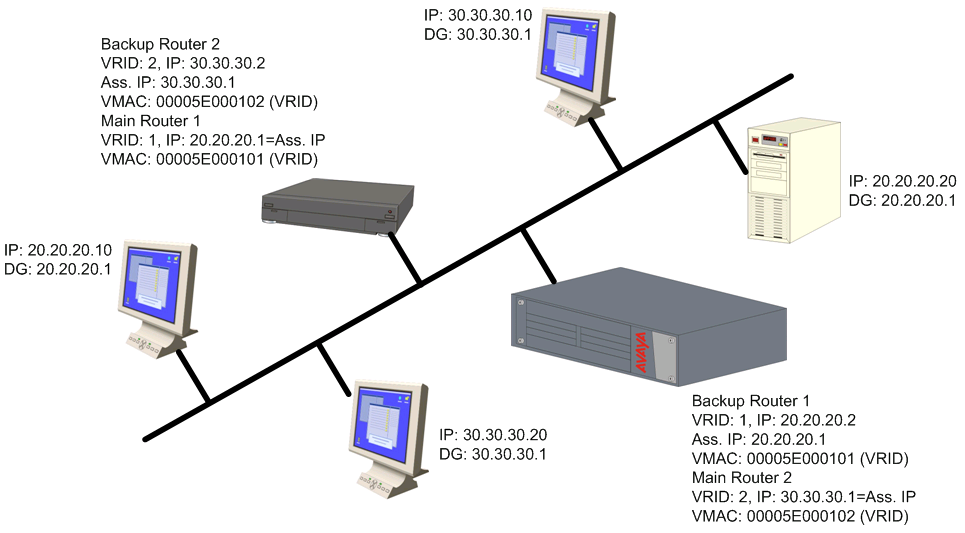
There is one main router on IP subnet 20.20.20.0, such as a Branch Gateway, switch, or any router that supports VRRP, and a backup router. You can configure more backup routers.
The Branch Gateway itself must have an interface on the IP subnetwork, for example, 20.20.20.2
Configure all the routers under the same VRID, for example,1. You must configure the routers per VLAN.
An assigned VRID must not be used in the network, even in a different VLAN
When router configuration is complete and the network is up, the main router for each virtual router is selected according to the following order of preference:
The virtual router IP address is also the router’s interface IP address
It has the highest priority (you can configure this parameter)
It has the highest IP address if the previous conditions do not apply
The virtual router IP address needs to be configured as the default gateway on the stations
The Main router advertises a six-byte Virtual MAC address, in the format 00.00.5E.00.01.02 VRID, as a response to the stations’ ARP requests
The redundant router uses a VRRP polling protocol to check the Main router integrity at one-second intervals (default). Otherwise, it is idle.
If the Main router fails, the redundant router that does not receive a response from four consecutive polling requests (default) takes over and starts to advertise the same Virtual MAC for ARP requests. Therefore, the stations will not detect any change either in the configured default gateway or at the MAC level.
VRRP has no provisions for routing database synchronization among the redundant routers. You must perform this manually, if needed.