AVAYA DOCUMENTATION CENTER
Find answers to your technical questions and learn how to use our products
Deploying and Upgrading Avaya G450 Branch Gateway
Adding or removing VoIP modules: MP20 and MP80
About this task
The G450 main board has four slots for VoIP engines. Each slot can accommodate either a Media Processor 20 (MP20) module or a Media Processor 80 (MP80) module. An MP20 provides 25 channels for G.711 and G.726 and 20 channels for G.729. An MP80 provides 80 channels.
The G450 supports a maximum of 320 active channels. Therefore, any combination of MP80 and MP20 in the four DSP slots can be supported.
The G450 prior to release 5.2.1 supports up to 240 channels. G450 v4 (4..x) does not support MP20 and MP80 VoIP modules.
Electrostatic discharge alert
Hold the modules only by the edges to avoid damage from static electricity. Do not touch the top or bottom of the circuit board. Wear an antistatic wrist ground strap when you handle module components. Connect the strap to an approved ground, such as an unpainted metal surface. Use an antistatic bag.
Caution:
The connector pins can get bent or damaged if you handle the module roughly or misalign the module before forcing the module into position.
There is no configuration necessary when you install an MP20 or MP80 module.
Procedure
- To insert an MP20 or MP80 module:
- Locate the MP20 or MP80 module slot.
The location differs depending on the hardware version of the G450 (see the figure and the figure).
Figure : 1. Location of MP20 and MP80 module slots in a G450 1.x 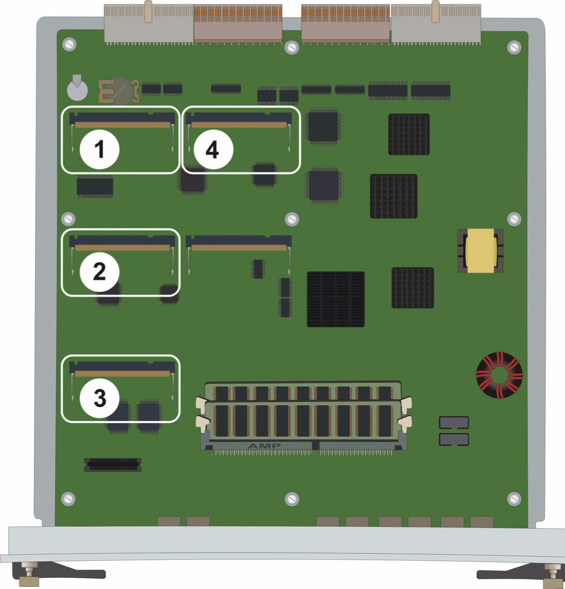
Table 1: Figure notes: 1
MP20 or MP80 module slot
2
MP20 or MP80 module slot
3
MP20 or MP80 module slot
4
MP20 or MP80 module slot
Figure : 2. Location of MP20 and MP80 module slots in a G450 2.x 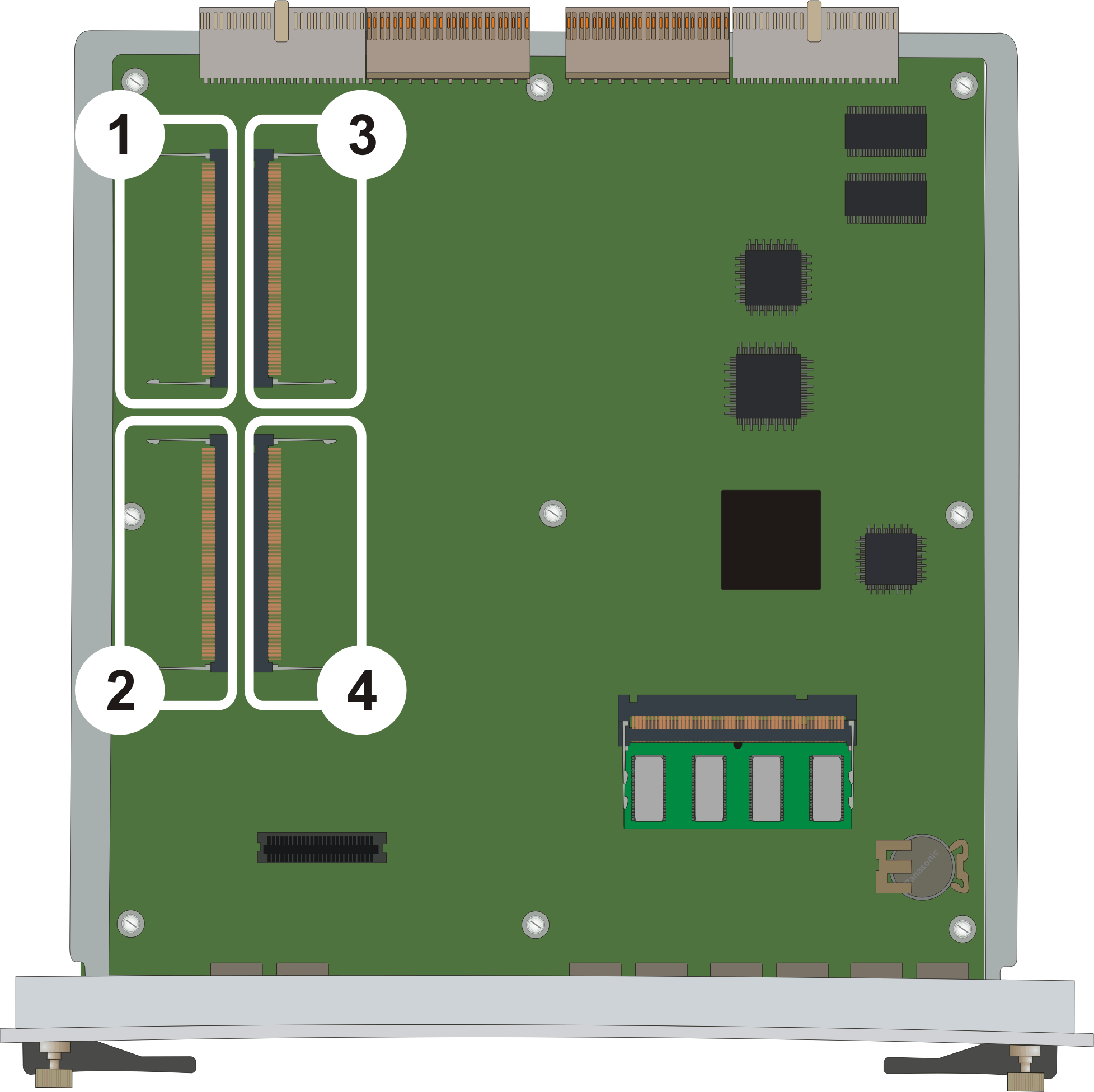
Table 2: Figure notes: 1
MP20 or MP80 module slot
2
MP20 or MP80 module slot
3
MP20 or MP80 module slot
4
MP20 or MP80 module slot
- Position the MP20 or MP80 module at a 45-degree angle to the main board, and start inserting it into an MP20 or MP80 slot (see the figure and the figure).
Figure : 3. Adding or removing an MP20 or MP80 module in a G450 1.x 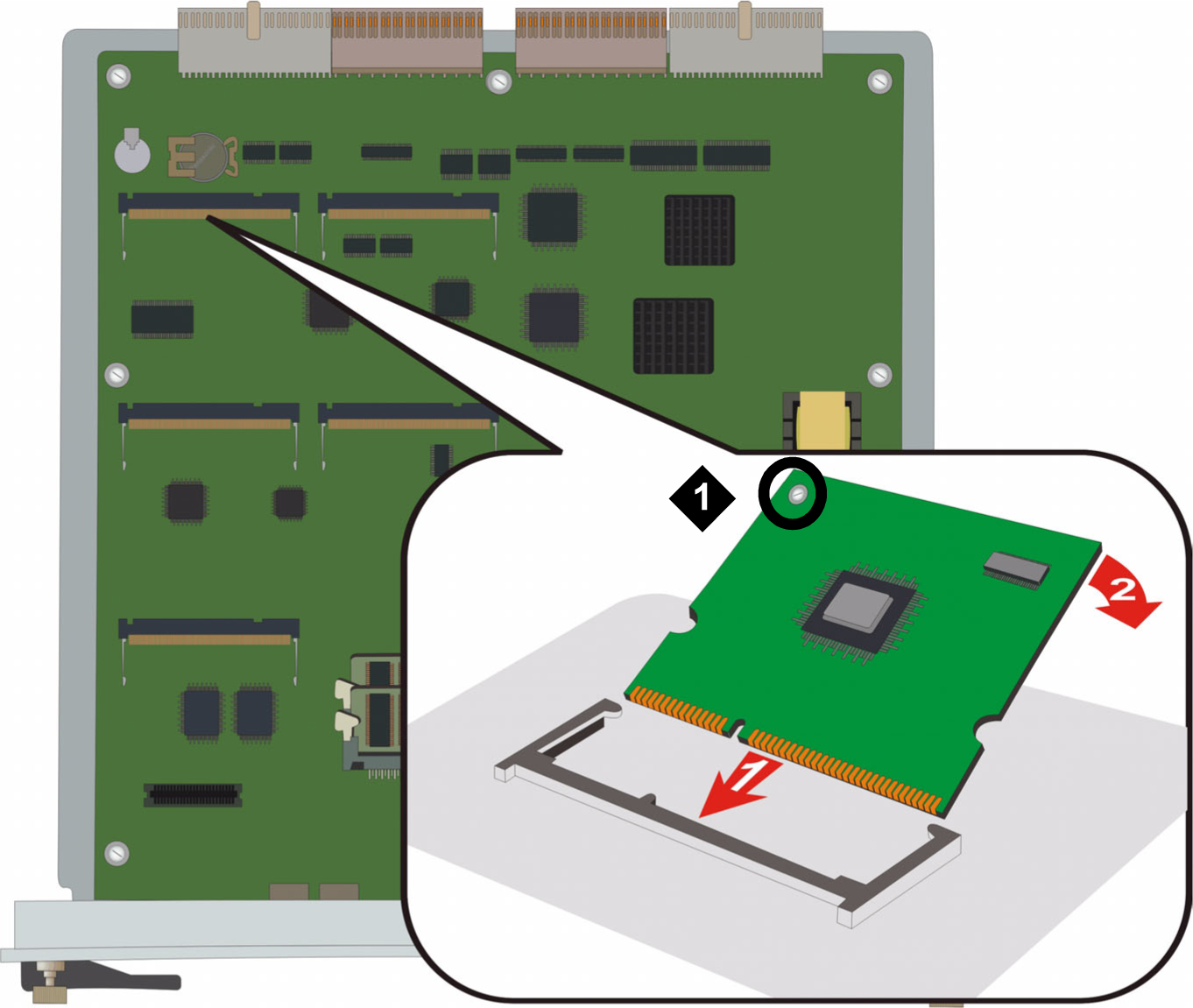
Table 3: Figure notes: 1
VoIP module locking screw
Figure : 4. Adding or removing an MP20 or MP80 module in a G450 2.x or 3.x 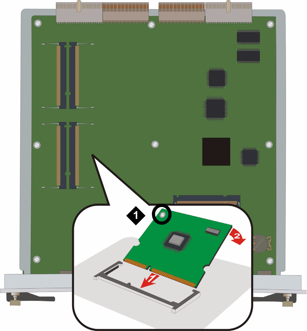
Table 4: Figure notes: 1
VoIP module locking screw
- Locate the MP20 or MP80 module slot.
- To remove an MP20 or MP80 module: