AVAYA DOCUMENTATION CENTER
Find answers to your technical questions and learn how to use our products
Avaya Aura® Communication Manager Alarms, Events, and Logs Reference
Configurations and maintenance
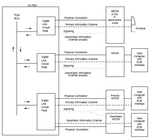
The MPDM provides an interface for Data Terminal Equipment terminals, and the MTDM (see note) provides an interface for Data Communications Equipment transmission equipment such as modems.
Note:
Early versions of these data modules were referred to as PDMs and TDMs, respectively. Later models are designed to provide various customer interfaces through the use of interchangeable interface modules and, therefore, are called modular data modules.
In the following discussion, the general term data module refers to MPDMs, MTDMs, and DAs. The PBX loop or digital link between a data module and the digital line port supports two logical information channels and one signaling channel. Data modules generally use the primary information channel for data communications and the signaling channel for dialing and call supervision. With 4-wire DCP, the secondary information channel can be used to support a second data module on a shared port.
Besides being used for data calls between terminals, computers, and data communications equipment, data modules also serve as interfaces to equipment associated with system features, such as System Administration, Station Message Detailed Recording, Message Center Service, Automatic Call Distribution, Distributed Communications System, and Audio Information Exchange. Maintenance for data modules associated with these latter services are covered by other MOs such as PMS-PRNT, JNL-PRNT, and PMS-LINK.
Maintenance of data modules is closely related to and interacts with Digital Line circuit pack maintenance, and test results for data modules can be affected by the health of the Digital Line PROCR. Keep this interaction in mind when investigating customer-reported problems with data modules.
Data modules provide a variety of option switches to allow the customer to select data rates, parity, keyboard dialing, local, and remote loopback. The DAA2 Data Adaptor has an AT (Hayes) type interface that allows selection of the above parameters as well as mode linked or standalone. An incorrect selection will not necessarily cause errors, alarms or test failures, but it can result in service disruption. See the installation manual provided with the data module for more information about those options.
This discussion occasionally refers to a station’s service state, defined as:
Out-of-Service |
The port, and thus the data module, have been removed from service. Causes for this include busyout of the port, removal of the Digital Line PROCR, and failure of the GPP NPE Crosstalk Test (#9). |
Disconnected |
The port is administered but the associated digital link does not respond. An administered port is put in a disconnected state after a system reboot or circuit pack insertion. This state persists until a link-reset-pass message is received from firmware on the PROCR. |
In-Service |
When switch software receives a link-reset-pass message from the port, the port is placed in service. If the link-reset-pass message is missed, and an off-hook message is received while the port is in the disconnected state, maintenance software will run an ID request test and put the port into service upon receiving a correct response. |