AVAYA DOCUMENTATION CENTER
Find answers to your technical questions and learn how to use our products
Avaya Aura® Communication Manager Alarms, Events, and Logs Reference
STRAT-3 (Stratum-3 Clock)
MO name in log |
Alarm level |
Initial command to run |
Full name of MO |
|---|---|---|---|
STRAT-3 |
MAJ MIN |
test synchronization |
Stratum-3 clock |
The Digital Synchronization Network Plan (PUB 60110) specifies a hierarchy of synchronization nodes consisting of Strata 1 to 4, where the public network’s sole Stratum-1 clock is the most accurate. Release 5r and later systems support both Stratum-3 and -4 operations. See Stratum-4 Synchronization for details on Stratum-4 operation.
A Stratum-3 clock derives its timing from two DS1 references connected to a Stratum-3 or better source. The Stratum-3 clock provides a holdover of at least 24 hours should both DS1 references fail. After 24 hours, the Stratum-3 clock still provides service but its accuracy may be degraded. The Digital Synchronization Network Plan (PUB 60110) requires that the Stratum-3 clock have duplicated components.
The Stratum-3 clock can be configured with only one DS1 input if one of the Clock Input cards is removed. Also, the Stratum-3 clock can free run use its internal clock without using DS1 inputs, if both Clock Input cards are removed.
The only operation that software can perform is a query of the alarm leads. The only recovery action that can be performed on a catastrophic failure of the Stratum-3 clock is using the local oscillator on the G4xx Media Gateway. Neither software nor the G4xx Media Gateway can request additional information about the health of the Stratum-3 clock other than the information provided by the alarm leads. Furthermore, neither the software nor the G4xx Media Gateway can request that the external clock switch references, change configuration, disable or enable, initialize, and so forth.
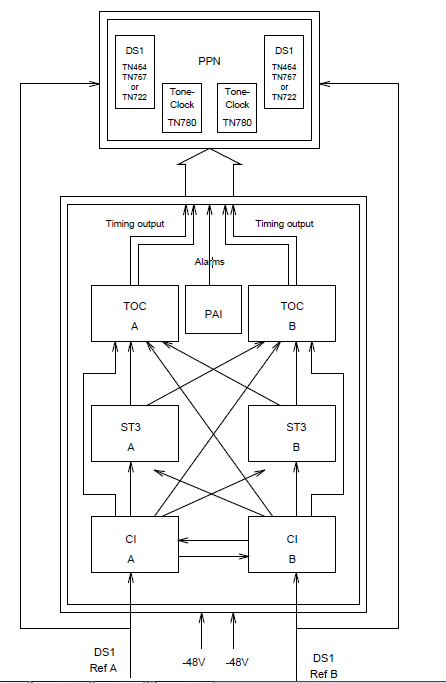
In the system, the Stratum-3 clock has been implemented as an external which follows the specification in PUB 60110 for Stratum 3. The only external Stratum-3 clock that is supported is the Telecom Solutions Digital Clock Distributor for Customer Premise Timing (DCD-CPT) Stratum-3 clock. Figure 73: Stratum-3 Clock Hardware Configuration shows how the Stratum-3 hardware configuration provides clock and alarm signals to the G4xx Media Gateway. The reference DS1 facilities connect directly to the Stratum-3 clock for timing purposes, but the DS1 data may be routed into the switch by using a Y connector H-600-274 G1 for the 50-pin DS1 end or H-600-274 G2 for the 15-pin DS1 end.