

AVAYA DOCUMENTATION CENTER
Find answers to your technical questions and learn how to use our products
Avaya Device Adapter Snap-in Reference
Geo-redundancy between MGCs of TDM endpoints and Device Adapter nodes
Geographic redundancy for Media Gateway Controllers (MGC) is configured by using Primary, Alternate 1, and Alternate 2 Avaya Breeze® platform clusters.
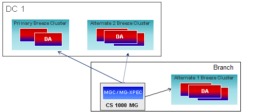
CS 1000 supports a single core server model and a 1+1 server model for high availability. If both the primary server and if configured, the secondary server fails to respond, the entire CS 1000 is unavailable. CS 1000 also supports a branch office model that provides fail over support if the CS 1000 is unavailable.
However, Device Adapter reuses the load balancer and multiple Device Adapter nodes to provide a broader coverage of fail-over registration. In a single-node cluster, the MGC tries to fail over to an alternate cluster if the load balancing server fails. In an N+1 node cluster, the MGC tries to fail over to an alternate cluster if the load balancing server and all the nodes in the cluster fail, or if the remaining functional nodes do not have the required capacity to support the fail over.
Device Adapter retains the existing CS 1000 logic for triple MGC registration fail over. During normal operating conditions, all devices are registered to the Primary cluster. If the Primary cluster fails, the MGC tries to register the endpoints with the Alt 1 cluster.
An MGC can be programmed to register with one of up to three different clusters: Primary, Alternate 1, and Alternate 2 clusters.
-
Registrations are given a predefined time to succeed. If the MGC is unable to succeed in that interval, the registration is declared failed.
-
The MGC always tries to register with the Primary cluster first.
-
If registration to the Primary cluster fails, MGC attempts to register with the Alternate 1 cluster.
-
If registration to the Alternate 1 cluster also fails, the MGC attempts to register with the Alternate 2 cluster.
-
If registration to the Alternate 2 cluster also fails, the MGC attempts to register with the Primary cluster.
All Avaya Breeze® platform clusters (all servers in a cluster), which are programmed as Primary, Alternate 1, or Alternate 2, receive the configuration of media gateways that are assigned to them. Therefore, the MGC can connect to any of the applicable server clusters and download the config files.
For example, assume that the following clusters are configured:
-
Cluster A: Servers 1,2,3
-
Cluster B: Servers 4,5,6
-
Cluster C: Servers 7,8,9
Assume that a specific MGC is configured as:
-
Primary: Cluster A
-
Alternate 1: Cluster C
-
Alternate 2: none
As a result, the configuration data for this MGC is present on servers 1, 2, and 3 (cluster A) and servers 7, 8, and 9 (cluster C). An administrator can enter the eth0 address for any of these servers to receive the proper config files.
Note:
-
MGCs can be configured with two features that may attempt to reconnect to the Primary cluster before connecting to Alternate 1.The Dual Homing feature defines an alternative connection route to the Primary cluster. If this feature is configured, the MGC will attempt to use this alternative connection route before connecting to Alternate 1.The short-term failure timer provides a mechanism for the Primary cluster to be unreachable for a time period before connecting to Alternate 1.
-
All MGC resources are reset when the connection transitions to a different cluster. This clears all ongoing calls.
-
After the Primary cluster (cluster 1) starts functioning, the MGC switches back to the Primary cluster.Alternatively, an administrator can manually configure the switch back option. In this case, the MGC remains registered with the Alternate cluster until the administrator manually runs a command to re-register with the Primary cluster.When the MGC fails over or switches back, all MGC resources are reset, which has an impact on endpoint registration and call handling. Hence, you can use the manual switch back option to switch back the MGC during a low traffic window to reduce the impact on endpoint registration and call handling.
In the following figure, the MGC that serves the TDM endpoints registers the endpoints through the N1 IP network to Device Adapter. The solid line represents a registration to the Primary cluster. The dashed and dotted lines indicate a possible registration to the Alt 1 and Alt 2 cluster respectively.
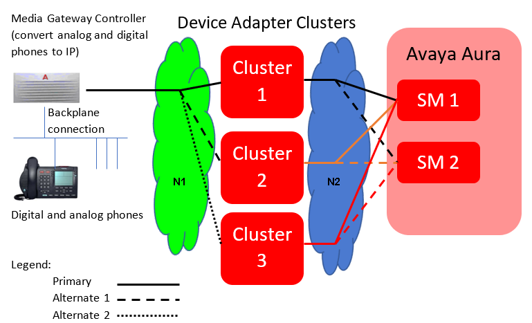
If there is a failure at cluster 1 (Primary cluster), either the N1 network, the cluster 1, or the N2 network has experienced an outage. The phone is isolated from Session Manager and the Avaya Aura® infrastructure. The phone tries registering with cluster 2 (Alt 1 cluster) by using the dashed line path.
If the registration attempt at cluster 2 fails, either the N1 network, the clusters 1 and 2, or the N2 network has experienced an outage. The endpoint is isolated from Session Manager and the Avaya Aura® infrastructure. The phone tries registering with cluster 3 (Alt 2 cluster) by using the dotted line path.
If none of the registration attempts succeed, the outage was probably too close to the phone to be resolved by HA and redundancy. For example, the IP cable that connects the MGC to the LAN segment may have failed, the line card for the phone may have failed, or other hardware issues may have occurred. The MGC tries to register the endpoints periodically till service personnel rectifies the cable or a LAN device failure and the MGC registers the endpoints.
Note that the MGC to Device Adapter is the single point with the capability of defining three options for support within the Device Adapter.