

AVAYA DOCUMENTATION CENTER
Find answers to your technical questions and learn how to use our products
Avaya Device Adapter Snap-in Reference
Troubleshooting MGC connection problems
Important:
Troubleshooting MGC connection related problems may require stopping and starting MGC and pbxserver service, which might have an impact on endpoint registrations and call handling.
For more information about the impact on endpoint registrations after stopping and starting the pbxserver service, see Maintenance commands.
Avaya recommends that you stop and start MGC and pbxserver service during the maintenance period to minimize endpoint registration and call handling problems.
- After MGC starts, MGC tries to establish RUDP connection with Device Adapter by using UDP port 15003.
ADDITIONAL INFORMATION:Run the following command at the MGC CLI command prompt to ensure that the ELAN and TLAN cables are plugged into MGC:ldb> ethportshowAn output similar to the following, with two active ports, appears:... Carrier detected on ports:6 ,7If not, then the problem might be with the cables or ethernet link and not because of socket error.
- Do the following to verify that the pbxserver process listens on UDP port 15003:
- Run the following command on the Avaya Breeze® platform CLI command prompt to verify that the pbxserver process listens on UDP port 15003:
ADDITIONAL INFORMATION:netstat -putanel | grep 15003A message similar to the following appears:udp 0 0 192.168.96.164:15003 0.0.0.0:* 700 894624883 26820/pbxserverIf pbxserver is not shown, go to Step 2 b.
- Run the following command on the Avaya Breeze® platform CLI command prompt to verify the pbxserver status:
ADDITIONAL INFORMATION:[root@breeze6 ~]# dasrvstart status pbxserverA message similar to the following appears:
? pbxserver.service - PBX Server for Avaya Device Adapter Snap-in

Loaded: loaded (/etc/systemd/system/pbxserver.service; enabled; vendor preset: disabled)

Active: active (running) since Thu 2018-11-15 16:56:08 MSK; 4 days ago

Main PID: 1934 (pbxserver)

CGroup: /system.slice/pbxserver.service

L-1934 /opt/Avaya/da/shared/bin/pbxserver

Nov 15 16:56:08 breeze6 systemd[1]: Started PBX Server for Avaya Device Adapter Snap-in.

Nov 15 16:56:08 breeze6 systemd[1]: Starting PBX Server for Avaya Device Adapter Snap-in... - Run the following commands on the Avaya Breeze® platform CLI command prompt to stop and start the pbxserver service:
ADDITIONAL INFORMATION:[root@breeze6 ~]# dasrvstart stop pbxserver[root@breeze6 ~]# dasrvstart start pbxserverRepeat Steps 2 and 2 a. If it does not give the expected result, go to Step 2 d.
- Run the following commands on the Avaya Breeze® platform CLI command prompt to enable debug logs for DSA and pxbserver:
ADDITIONAL INFORMATION:[root@breeze6 ~]# syslogLevelSet dsa tDSA DEBUGRun the following command to ensure that log level changes are applied:syslogShow
- Do the following on System Manager to enable debug logs for Device Adapter snap-in:
ADDITIONAL INFORMATION:
-
On the System Manager web console, click .
-
Select the appropriate cluster and server.
-
In the Service field, click Device Adapter.
-
In the Log Level field, click DEBUG.
-
- After enabling the debug log, go to Step 2 c and collect logs for 5 to 10 minutes, and then do the following to extract logs from the Avaya Breeze® platform:
ADDITIONAL INFORMATION:collect /var/log/Avaya/services/DeviceAdapter/DeviceAdapter.logcollect /var/log/Avaya/services/DeviceAdapter/dsa.logcollect /var/log/Avaya/services/DeviceAdapter/ss_common.log
- Run the following commands on the Avaya Breeze® platform CLI command prompt to investigate error logs:
ADDITIONAL INFORMATION:[root@breeze6 ~]# cat /var/log/Avaya/services/DeviceAdapter/DeviceAdapter.log | grep -i "error\|warn"[root@breeze6 ~]# cat /var/log/Avaya/services/DeviceAdapter/dsa.log | grep -i "error\|warn"[root@breeze6 ~]# cat /var/log/Avaya/services/DeviceAdapter/ss_common.log | grep -i "error\|warn"
- Run the following command on the Avaya Breeze® platform CLI command prompt to verify that the pbxserver process listens on UDP port 15003:
- Do the following to verify that port 15003 and 15000 are open:
- On the System Manager web console, click .
- In Cluster State, ensure that the cluster state is set to “Accept” corresponding to Avaya Breeze® platform cluster that you are working on.
- Run the following command to verify that port 15003 is open:
ADDITIONAL INFORMATION:[root@breeze6 ~]# ce fwall show 15003/udpThe following message appears:15003/udp on
- If port 15003 is disabled, run the following command to enable port 15003:
ADDITIONAL INFORMATION:[root@breeze6 ~]# ce fwall on 15003/udp
- Run the following command to verify that port 15000 is open:
ADDITIONAL INFORMATION:[root@breeze6 ~]# ce fwall show 15000/tcpThe following message appears:15000/tcp on
- If port 15000 is disabled, run the following command to enable port 15000:
ADDITIONAL INFORMATION:[root@breeze6 ~]# ce fwall on 15000/tcp
- Do the following to verify that packets from MGC reach the Avaya Breeze® platform server:
- Log in to Avaya Breeze® platform as root user and run tshark.
ADDITIONAL INFORMATION:Ensure that there are no "administratively prohibited“ or “host unreachable” messages. These messages appear in situations such as the ports are closed or if there is a firewall problem.
- Run the following command, and then restart MGC:
ADDITIONAL INFORMATION:[root@breeze6 ~]# tshark -i any "host 192.168.23.24"Where the IP address is MGC ELAN IP.The following message appears:
1 0.000000000 192.168.23.24 -> 192.168.96.178 UDP 62 Source port: 15003  Destination port: 15003

2 0.000218436 192.168.96.178 -> 192.168.23.24 UDP 50 Source port: 15003  Destination port: 15003
The following message appears in case of dropped packets:1 0.000000000 192.168.127.91 -> 192.168.96.178 UDP 62 Source port: 15003 Destination port: 15003
2 0.000078870 192.168.96.178 -> 192.168.127.91 ICMP 78 Destination unreachable (Port unreachable)If you do not see packets at all, there might be a network problem.If you see "administratively prohibited" packets, then do the following to put the Avaya Breeze® platform cluster to Deny, and then to Accept mode.-
On the System Manager web console, click .
-
In Cluster State, verify the state of the Avaya Breeze® platform cluster.
-
- Verify that the custom firewall rule is set to Off on MGC.
ADDITIONAL INFORMATION:Custom firewall rule might be On if previously the custom firewall rule was set by the CS 1000 call server. Do the following:
-
Run the following command to verify the port access status:ldb> portAccessStatusIf the following message appears, go to Step b:
Global status: custom

Local state: custom -
Run the following command to turn off custom firewall rule:ldb> portAccessOff
-
- Log in to Avaya Breeze® platform as root user and run tshark.
- Do the following to verify the rudp connection status on Avaya Breeze® platform and MGC:
- Run the following command on the Avaya Breeze® platform CLI command prompt to verify the rudp connection status:
ADDITIONAL INFORMATION:[root@br3937 ~]# vxShell pbxserver rudpShowThe following message appears if the connection is proper:
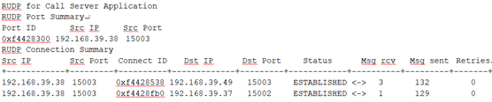 The following message appears if the system cannot find the pbxserver process:value = 0xf56fe080 (4117749888)To troubleshoot the problem, repeat Steps 2 b through 2 g.
 - Run the following command on the MGC to verify the rudp connection status:
ADDITIONAL INFORMATION:ldb> rudpShowThe following message appears if the connection is proper:
 If a message similar to the following appears, verify the IPSEC status on Device Adapter and MGC:
- Run the following command on the Avaya Breeze® platform CLI command prompt to verify the rudp connection status:
- Verify if FIPS mode is enabled and MGC runs old loadware from Avaya Device Adapter Snap-in. The old MGC version does not support the strong ciphers that FIPS mode requires.
ADDITIONAL INFORMATION:
-
Temporarily disable FIPS mode.
-
Upgrade MGCs to updated loadware lineup and enable FIPS mode.
-
- Verify if IPSec is enabled on both the MGC and Avaya Device Adapter Snap-in side.
ADDITIONAL INFORMATION:On MGC issue isssShow command:
ldb> isssShowOn Avaya Device Adapter Snap-in side:-
In the Enable IPsec for Media Gateways field, in Effective Value is set to Yes.
-
The ipsec status command displays on Avaya Breeze® server.
[root@breeze5 ~]# ipsec statuswhack: Pluto is not running (no "/run/pluto/pluto.ctl")
If IPSec is disabled on both the Avaya Breeze® server and Avaya Device Adapter Snap-in then go to the next chapter. Otherwise, perform the following troubleshoot steps:-
Manually synchronize the IPSec configuration if:
-
IPSec is disabled on MGC but enabled on Avaya Device Adapter Snap-in.
-
IPSec configuration is not synchronized on the MGC or changed on Avaya Device Adapter Snap-in side while MGC was down.
-
-
Make sure that the Primary Server IP (through mgcinfoshow) command corresponds to what is configured in SMGR for the MGC:
-
On System Manager, click .
-
On the Device Adapter tab, make sure you select the correct cluster.
-
-
Make sure that if the Avaya Device Adapter Snap-in cluster is Cluster IP (two or more servers) then MGC Primary Server IP is set to Cluster IP. If Avaya Device Adapter Snap-in cluster consists of a single server, then MGC Primary Server IP is set to SecureLink IP address (eth1).
-
Verify if the FIPS mode is enabled on the Avaya Breeze® server. Do the following:
-
Avaya Device Adapter Snap-in version must be 8.1.3 or later.
-
MGC loadware version should match with ADA 8.1.3 lineup.
-
On MGC, perform
swVersionShowcommand. -
On Avaya Breeze® server, verify the loadware files in "ls -l /opt/Avaya/da/mgc/loadware/current/".
-
-
Compare the Avaya Device Adapter Snap-in versions.
-
If any of the above values is true, then MGC fails to connect with Avaya Device Adapter Snap-in. Upgrade Avaya Device Adapter Snap-in to 8.1.3 version. -
- After RUDP the link is established, MGC sends the "call server info request" message over the rudp link.
ADDITIONAL INFORMATION:This is indicated with the following message in the logs:Sending message to Call Server to get csinfo.If MGC receives a response, the following message appears:Successfully got call server information from Primary.
- Run the following command to enable dsa debug logs and verify if dsa receives messages in the dsa log when Sending message to Call Server to get csinfo. messages appear on MGC:
ADDITIONAL INFORMATION:syslogLevelSet dsa tDSA 7 ; tail -f /var/log/Avaya/services/DeviceAdapter/dsa.logThe following example error message indicates that SSK keys between MGC and Avaya Breeze® platform are not generated:Nov 16 12:03:36 greenedpeccm dsa: ERROR: [13077] CSSHClient::Connect(): authentication to host 135.20.225.84 failed with error code -16, message:
- Go to Step 5 to verify the network connectivity and rudp link.
- Run the following command to enable dsa debug logs and verify if dsa receives messages in the dsa log when Sending message to Call Server to get csinfo. messages appear on MGC:
- After a response to the request in Step 8 a is received, MGC establishes TCP link on port 15000 with Device Adapter.
ADDITIONAL INFORMATION:Upon successful connection, the following message appears:SYS: PBX TCP link established with ..Run the following command on the Avaya Breeze® platform CLI command prompt to verify the TCP link:[root@breeze5 ~]# vxShell pbxserver tcpLinkShowThe following message appears for a successful connection:192.168.128.144 |0xf4228fb0|18 |0 |0 | Link OKIf the "Failed to open TCP network connection to CS" message appears, do the following:
- Verify that the TCP packets reach Avaya Breeze® platform as in Step 4.
- Run the following command on the Avaya Breeze® platform CLI command prompt to enable debug logs and contact Avaya Support:
ADDITIONAL INFORMATION:[root@breeze5 ~]# syslogLevelSet pbxserver tRUDP 7[root@breeze5 ~]# syslogLevelSet pbxserver tvtServer 7[root@breeze5 ~]# syslogLevelSet pbxserver tvtServerRx 7
- After TCP link is up, MGC sends a ServerOnline message. Device Adapter responds with a ServerStatus message.
ADDITIONAL INFORMATION:Run the following mgcShow command to verify that Device Adapter has added MGC to the server list:root@breeze14 DeviceAdapter]# mgcShowIf you receive the following message, the Received server status for link Primary with status 0 log entry appears on MGC:
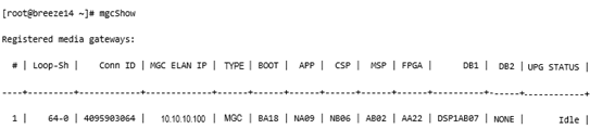 You might not receive the preceding message if MGC is not configured on System Manager.Do one of the following:
-
Verify the MGC configuration in on System Manager.
-
If MGC is configured properly, restart the Device Adapter Snap-In.
-
Examine the dsa tDSA debug logs.
-
- After the ServerStatus message is received, MGC waits for Device Adapter to upload the mgcdb.xml file to /u/db/ over SFTP and send a FileUploaded message upon completion.
ADDITIONAL INFORMATION:After this, dsa logs the following debug log entry:CServerController::SendServiceFileUpdated()MGC shows the following messages for companding law and loop/shelf.09/10/2018 15:21:11 LOG0006 tMgcVgwAppStart: Loop/shelf is set to 0-009/10/2018 15:21:11 LOG0006 tMgcVgwAppStart: Companding law is set to a-lawIf Device Adapter cannot upload the mgcdb.xml file, it shows the following message and raises an alarm:Cannot transfer XML config file to MGC.Examine the log entries to investigate the reason. The most common reason is that MGC does not have the login set to admin2 and password set to 0000.MGC waits for FileUploaded message for 75 seconds. After that, MGC tries to read the existing /u/db/mgcdb.xml file on the disk. Otherwise, MGC restarts.When the FileUploaded message is received, MGC reads the mgcdb.xml file to retrieve loop/shelf. MGC uses loop/shelf to further register the DSP channels, IPE cards, and units.
- MGC detects IPE cards and units.
ADDITIONAL INFORMATION:The following is an example of log messages on MGC:09/10/2018 15:21:12 LOG0006 CLAN: Slot: 3, Card Type: XMLC (24), Signaling Type: A10 (2), Map Type: 3The following is an example of a debug log message in dsa.log:CIPECardManager::OnIPECardPlugged(): 0-0-3The dsa log message is for loop and shelf that MGC retrieves from the mgcdb.xml file.
- Run the following command to verify the card and unit detection status on Device Adapter:
ADDITIONAL INFORMATION:ipeShow <loop>-<shelf>The following message appears:
[root@breeze5 ~]# ipeShow 0-0

Detected IPE cards for media gateway: 0 0

Card Slot  |    Type   | Status  |

------------+-----------+---------+

3 | MLC | ok | - Do one of the following if the ipeShow command does not show any cards, even though the MGC logs show the detected cards:
ADDITIONAL INFORMATION:
-
MGC might lose and then re-establish pbxlink. In this case, the card and unit status is not synced with Device Adapter.
-
Unplug and plug in the card again.
When Device Adapter receives a card detection message, it sends initialization messages and turns off the red LED on the faceplate.A red LED indicates that the card is currently not recognized by Device Adapter.ALC card is also initialized with a companding law. -
- Run the following command to verify the card and unit detection status on Device Adapter:
- MGC starts the VGW application that initializes the DSP daughterboards and starts registering channels.
- Run the following command to verify VGW channel registration status on Device Adapter:
ADDITIONAL INFORMATION:vgwShow <loop>-<shelf>The following message appears:
[root@breeze5 ~]# vgwShow 0-0

VGW TN    |       IP       |  Port  |   Phone TN

--------------|----------------+--------|-------------

000-00-11-00 |192.168.128.146 |   5392 |000-00-03-00

000-00-11-01 |192.168.128.146 |   5394 |

000-00-11-02 |192.168.128.146 | 5396 | - If there are no listed channels, run the following command on MGC to force register the channels:
ADDITIONAL INFORMATION:vgwRegisterAllDevice Adapter sends tone channel initialization messages. One of its parameters is companding law that is used to init TNC device.When ALC card is detected, Device Adapter tries to register all its 16 units.
- Run the following command to verify VGW channel registration status on Device Adapter:
- DLC card units are detected individually. Run the following command to verify the DLC card units:
ADDITIONAL INFORMATION:ipeShow <loop>-<shelf>-<card>If a DLC unit shows as detected but the set is not working, verify if the DLC unit is configured in System Manager and Communication Manager station.
- Run the following commands to verify the set registration status:
ADDITIONAL INFORMATION:dsaShowendpointShowThe endpointShow command can take TN or extension.An output similar to the following appears:
