

AVAYA DOCUMENTATION CENTER
Find answers to your technical questions and learn how to use our products
Avaya Device Adapter Snap-in Reference
Configuring the station definition for the MDA user extension
The template type that you use to define the station definition depends on whether you want to configure the phone as a UC, call center (CC), or a CTI controlled phone:
|
Phone type
|
Station definition template
|
|---|---|
|
Unified Communications phone
|
CS1K_IP
|
|
Call center (CC) phone in Call Center Elite
|
CS1K_IPCC
|
|
Phone in Avaya Aura® Contact Center
|
CS1K_IP
|
|
CTI controlled phone along with Call Center Elite
|
|
|
CTI controlled phone along with Avaya Aura® Contact Center
|
CS1K_IP
|
- Do any one of the following to configure the station definition for the MDA user extension:
-
Configure the station definition at the Communication Manager CLI command prompt.For more information, see the Avaya Aura® Communication Manager Feature Description and Implementation guide.
-
On System Manager, click and configure the station definition.
-
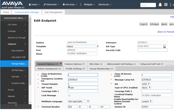
The preceding screen shot shows the endpoint defined as a 2050 soft client. An endpoint that has the appropriate feature content mapping to the 2050 soft client can SIP register at this extension.
However, a 96x1, a J-Series, or a non-CS 1000 soft client has a moderately different user experience as compared to the Device Adapter endpoint.
The Transfer button is an example of this difference:
-
The Transfer button on both UNIStim endpoint and Avaya Aura® SIP endpoint appears as a context-sensitive soft key. This Transfer soft key is available only when the user is on a call and has the resources to transfer the call.
-
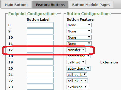
Device Adapter maps the Transfer soft key to include the call appearance and the Transfer function in a single button. Device Adapter sends the applicable message for the current context.The following screen shot shows a programmed Transfer soft key at position 17 on the Feature Buttons tab.The Transfer soft key configuration is for a 1140 phone that is on Device Adapter. Device Adapter considers this as both a Transfer soft key and a call appearance button. In the following example, buttons 0 through 11 are programmable feature keys and buttons 17 through 23 are soft keys.
-
An Avaya Aura® SIP endpoint uses the Transfer soft key, which puts the current call on hold and selects a second call appearance.The following screen shot on the left shows the screen of a 96x1 phone and the screen shot on the right shows the screen of a UNIStim phone.On the 96x1 phone, the fourth button labeled transfer is an additional call appearance. This transfer button is mapped to the Transfer soft key on the UNIStim station.The Transfer soft key appears at the bottom of both the UNIStim and 96x1 endpoint screens only during an active call. The user must press the Transfer soft key to initiate the transfer and enter the destination number. The user must then press the Complete soft key to complete the transfer.
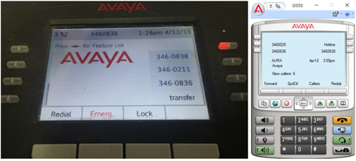
The Avaya Aura® SIP endpoint moves all the call appearances to the first screen, which is the Phone screen, with the call appearance for the Transfer button placed last.
Note that all feature buttons on the CS 1000 station appear on the second screen, which is the Features screen, on the 96x1. For example, the Forward feature button.